|
|
| Line 1: |
Line 1: |
| − | Haithem's logbook for developing neutron sensitive TGEM detector
| + | [[HM_2014]] |
| | | | |
| | + | [[2012]] |
| | | | |
| − | [[2009]] | + | [[2011]] |
| | | | |
| − | =01/05/10=
| + | [[2010]] |
| | | | |
| − | ;Simulation of the mass distribution spectra for Thorium-232 for 7.5 MeV:
| + | [[2009]] |
| | | | |
| − | [[File:Energy_7.5_a_include1.jpg|100px]] [[File:Energy_7.5_a_biggerthan1.jpg|100px]]
| + | =Dissertation= |
| | | | |
| − | (1st figure is the full spectrum but the 2nd one for a>1)
| + | ;11/01/2015 |
| | | | |
| − | Three kinds of events tracked :
| + | Measurements |
| | | | |
| − | <pre>
| |
| − | *********************************************************************************************************
| |
| − | * G4Track Information: Particle = neutron, Track ID = 1, Parent ID = 0
| |
| − | *********************************************************************************************************
| |
| | | | |
| − | Step# X Y Z KineE dEStep StepLeng TrakLeng Volume Process
| + | [[File:measurements_1.pdf]] |
| − | 0 0 fm 0 fm -80 cm 7.5 MeV 0 eV 0 fm 0 fm World initStep
| + | [[File:measurements_2.pdf]] |
| − | 1 0 fm 0 fm -5 mm 7.5 MeV 0 eV 79.5 cm 79.5 cm World Transportation
| + | [[File:measurements_3.pdf]] |
| − | 2 0 fm 0 fm -3.06 mm 0 eV 0 eV 1.94 mm 79.7 cm Target NeutronInelastic
| |
| − | :----- List of 2ndaries - #SpawnInStep= 3(Rest= 0,Along= 0,Post= 3), #SpawnTotal= 3 ---------------
| |
| − | : 0 fm 0 fm -3.06 mm 578 keV 1
| |
| − | : 0 fm 0 fm -3.06 mm 291 keV 1
| |
| − | : 0 fm 0 fm -3.06 mm 35.5 keV 231
| |
| − | :----------------------------------------------------------------- EndOf2ndaries Info ---------------
| |
| | | | |
| − | *********************************************************************************************************
| |
| − | * G4Track Information: Particle = Th231[14330.9], Track ID = 4, Parent ID = 1
| |
| − | *********************************************************************************************************
| |
| | | | |
| − | Step# X Y Z KineE dEStep StepLeng TrakLeng Volume Process
| |
| − | 0 0 fm 0 fm -3.06 mm 35.5 keV 0 eV 0 fm 0 fm Target initStep
| |
| − | 1 251 um 2.7 mm 5 mm 35.5 keV 0 eV 8.5 mm 8.5 mm Target Transportation
| |
| − | 2 2.43 mm 2.61 cm 7.5 cm 35.5 keV 0 eV 7.39 cm 8.24 cm World Transportation
| |
| − | 3 3.17 mm 3.41 cm 9.87 cm 35.5 keV 0 eV 2.5 cm 10.7 cm Tracker StepLimiter
| |
| − | 4 3.91 mm 4.2 cm 12.2 cm 35.5 keV 0 eV 2.5 cm 13.2 cm Tracker StepLimiter
| |
| − | 5 4.65 mm 4.99 cm 14.6 cm 35.5 keV 0 eV 2.5 cm 15.7 cm Tracker StepLimiter
| |
| − | 6 5.39 mm 5.79 cm 17 cm 35.5 keV 0 eV 2.5 cm 18.2 cm Tracker StepLimiter
| |
| − | 7 6.12 mm 6.58 cm 19.3 cm 35.5 keV 0 eV 2.5 cm 20.7 cm Tracker StepLimiter
| |
| − | 8 6.86 mm 7.37 cm 21.7 cm 35.5 keV 0 eV 2.5 cm 23.2 cm Tracker StepLimiter
| |
| − | 9 6.98 mm 7.5 cm 22.1 cm 35.5 keV 0 eV 3.94 mm 23.6 cm Tracker Transportation
| |
| − | 10 2.5 cm 26.9 cm 80 cm 35.5 keV 0 eV 61.1 cm 84.7 cm OutOfWorld Transportation
| |
| | | | |
| − | *********************************************************************************************************
| + | Conclusion |
| − | * G4Track Information: Particle = neutron, Track ID = 3, Parent ID = 1
| |
| − | *********************************************************************************************************
| |
| | | | |
| − | Step# X Y Z KineE dEStep StepLeng TrakLeng Volume Process
| + | [[File:conc.pdf]] |
| − | 0 0 fm 0 fm -3.06 mm 291 keV 0 eV 0 fm 0 fm Target initStep
| |
| − | 1 -624 um -1.4 mm -5 mm 291 keV 0 eV 2.47 mm 2.47 mm Target Transportation
| |
| − | 2 -25.6 cm -57.4 cm -80 cm 291 keV 0 eV 1.01 m 1.02 m OutOfWorld Transportation
| |
| | | | |
| − | *********************************************************************************************************
| + | =alpha calibration= |
| − | * G4Track Information: Particle = neutron, Track ID = 2, Parent ID = 1
| |
| − | *********************************************************************************************************
| |
| | | | |
| − | Step# X Y Z KineE dEStep StepLeng TrakLeng Volume Process
| + | [[File:ch_alphaE.png | 150px]] |
| − | 0 0 fm 0 fm -3.06 mm 578 keV 0 eV 0 fm 0 fm Target initStep
| |
| − | 1 434 um -5 mm 811 um 578 keV 0 eV 6.34 mm 6.34 mm Target Transportation
| |
| − | 2 6.94 cm -80 cm 61.6 cm 578 keV 0 eV 1.01 m 1.01 m OutOfWorld Transportation
| |
| − | </pre>
| |
| | | | |
| − | ;and
| |
| − | <pre>
| |
| − | *********************************************************************************************************
| |
| − | * G4Track Information: Particle = neutron, Track ID = 1, Parent ID = 0
| |
| − | *********************************************************************************************************
| |
| | | | |
| − | Step# X Y Z KineE dEStep StepLeng TrakLeng Volume Process
| + | [[File:Raw_data_all.pdf]] |
| − | 0 0 fm 0 fm -80 cm 7.5 MeV 0 eV 0 fm 0 fm World initStep
| |
| − | 1 0 fm 0 fm -5 mm 7.5 MeV 0 eV 79.5 cm 79.5 cm World Transportation
| |
| − | 2 0 fm 0 fm -2.2 mm 0 eV 0 eV 2.8 mm 79.8 cm Target NeutronInelastic
| |
| − | :----- List of 2ndaries - #SpawnInStep= 2(Rest= 0,Along= 0,Post= 2), #SpawnTotal= 2 ---------------
| |
| − | : 0 fm 0 fm -2.2 mm 1.91 MeV 1
| |
| − | : 0 fm 0 fm -2.2 mm 19.7 keV 232
| |
| − | :----------------------------------------------------------------- EndOf2ndaries Info ---------------
| |
| | | | |
| − | *********************************************************************************************************
| |
| − | * G4Track Information: Particle = Th232[5594.3], Track ID = 3, Parent ID = 1
| |
| − | *********************************************************************************************************
| |
| | | | |
| − | Step# X Y Z KineE dEStep StepLeng TrakLeng Volume Process
| + | The main peaks are for the following channel numbers, |
| − | 0 0 fm 0 fm -2.2 mm 19.7 keV 0 eV 0 fm 0 fm Target initStep
| |
| − | 1 -560 um -4.06 mm 5 mm 19.7 keV 0 eV 8.29 mm 8.29 mm Target Transportation
| |
| − | 2 -6 mm -4.35 cm 7.5 cm 19.7 keV 0 eV 8.06 cm 8.88 cm World Transportation
| |
| − | 3 -7.69 mm -5.58 cm 9.67 cm 19.7 keV 0 eV 2.5 cm 11.4 cm Tracker StepLimiter
| |
| − | 4 -9.37 mm -6.81 cm 11.8 cm 19.7 keV 0 eV 2.5 cm 13.9 cm Tracker StepLimiter
| |
| − | 5 -1.03 cm -7.5 cm 13.1 cm 19.7 keV 0 eV 1.42 cm 15.3 cm Tracker Transportation
| |
| − | 6 -6.23 cm -45.2 cm 80 cm 19.7 keV 0 eV 77 cm 92.3 cm OutOfWorld Transportation
| |
| | | | |
| − | *********************************************************************************************************
| + | You need to redo these plots in publication quality with proper axis labels containing units. |
| − | * G4Track Information: Particle = neutron, Track ID = 2, Parent ID = 1
| |
| − | *********************************************************************************************************
| |
| | | | |
| − | Step# X Y Z KineE dEStep StepLeng TrakLeng Volume Process
| + | [[File:ch_alphap1.png | 150px]] |
| − | 0 0 fm 0 fm -2.2 mm 1.91 MeV 0 eV 0 fm 0 fm Target initStep
| + | [[File:ch_alphap2.png | 150px]] |
| − | 1 689 um 5 mm 2.07 mm 1.91 MeV 0 eV 6.61 mm 6.61 mm Target Transportation
| |
| − | 2 11 cm 80 cm 68.1 cm 1.91 MeV 0 eV 1.05 m 1.06 m OutOfWorld Transportation
| |
| | | | |
| − | </pre>
| + | {| border="1" cellpadding="4" |
| | + | |- |
| | + | |channel Number|| Energy Upper limit (MeV)|| Energy lower limit (MeV)|| average energy (MeV)|| Notes |
| | + | |- |
| | + | | 4828 || 4.90 || 4.79 || 4.85 +_ 0.02 || |
| | + | |- |
| | + | | 4869 || 4.94 || 4.83 || 4.88 +_ 0.02 || |
| | + | |} |
| | | | |
| − | ;In addition to the fission event:
| + | =Gamma Spectrum for U-233= |
| − | <pre>
| |
| − | *********************************************************************************************************
| |
| − | * G4Track Information: Particle = neutron, Track ID = 1, Parent ID = 0
| |
| − | *********************************************************************************************************
| |
| | | | |
| − | Step# X Y Z KineE dEStep StepLeng TrakLeng Volume Process
| + | [[File:gamma_spect.png | 150px]] |
| − | 0 0 fm 0 fm -80 cm 7.5 MeV 0 eV 0 fm 0 fm World initStep
| |
| − | 1 0 fm 0 fm -5 mm 7.5 MeV 0 eV 79.5 cm 79.5 cm World Transportation
| |
| − | 2 0 fm 0 fm 1.2 mm 0 eV 0 eV 6.2 mm 80.1 cm Target NeutronInelastic
| |
| − | :----- List of 2ndaries - #SpawnInStep= 7(Rest= 0,Along= 0,Post= 7), #SpawnTotal= 7 ---------------
| |
| − | : 0 fm 0 fm 1.2 mm 138 keV 1
| |
| − | : 0 fm 0 fm 1.2 mm 2.37 MeV 1
| |
| − | : 0 fm 0 fm 1.2 mm 78.3 MeV 123
| |
| − | : 0 fm 0 fm 1.2 mm 1.83 MeV 1
| |
| − | : 0 fm 0 fm 1.2 mm 4.17 MeV 1
| |
| − | : 0 fm 0 fm 1.2 mm 653 keV 1
| |
| − | : 0 fm 0 fm 1.2 mm 89.1 MeV 105
| |
| − | :----------------------------------------------------------------- EndOf2ndaries Info ---------------
| |
| | | | |
| − | *********************************************************************************************************
| + | = Last runs= |
| − | * G4Track Information: Particle = Mo105[14330.9], Track ID = 8, Parent ID = 1
| |
| − | *********************************************************************************************************
| |
| | | | |
| − | Step# X Y Z KineE dEStep StepLeng TrakLeng Volume Process
| |
| − | 0 0 fm 0 fm 1.2 mm 89.1 MeV 0 eV 0 fm 0 fm Target initStep
| |
| − | 1 5 mm 442 um 1.9 mm 89.1 MeV 0 eV 5.07 mm 5.07 mm Target Transportation
| |
| − | 2 80 cm 7.07 cm 11.4 cm 89.1 MeV 0 eV 80.6 cm 81.1 cm OutOfWorld Transportation
| |
| − |
| |
| − | *********************************************************************************************************
| |
| − | * G4Track Information: Particle = neutron, Track ID = 7, Parent ID = 1
| |
| − | *********************************************************************************************************
| |
| − |
| |
| − | Step# X Y Z KineE dEStep StepLeng TrakLeng Volume Process
| |
| − | 0 0 fm 0 fm 1.2 mm 653 keV 0 eV 0 fm 0 fm Target initStep
| |
| − | 1 5 mm 1.85 mm 719 um 653 keV 0 eV 5.35 mm 5.35 mm Target Transportation
| |
| − | 2 80 cm 29.7 cm -7.55 cm 653 keV 0 eV 85.1 cm 85.7 cm OutOfWorld Transportation
| |
| − |
| |
| − | *********************************************************************************************************
| |
| − | * G4Track Information: Particle = neutron, Track ID = 6, Parent ID = 1
| |
| − | *********************************************************************************************************
| |
| − |
| |
| − | Step# X Y Z KineE dEStep StepLeng TrakLeng Volume Process
| |
| − | 0 0 fm 0 fm 1.2 mm 4.17 MeV 0 eV 0 fm 0 fm Target initStep
| |
| − | 1 4.44 mm 1.75 mm -5 mm 4.17 MeV 0 eV 7.82 mm 7.82 mm Target Transportation
| |
| − | 2 57.4 cm 22.6 cm -80 cm 4.17 MeV 0 eV 1 m 1.01 m OutOfWorld Transportation
| |
| − |
| |
| − | *********************************************************************************************************
| |
| − | * G4Track Information: Particle = neutron, Track ID = 5, Parent ID = 1
| |
| − | *********************************************************************************************************
| |
| − |
| |
| − | Step# X Y Z KineE dEStep StepLeng TrakLeng Volume Process
| |
| − | 0 0 fm 0 fm 1.2 mm 1.83 MeV 0 eV 0 fm 0 fm Target initStep
| |
| − | 1 2.07 mm 3.07 mm 5 mm 1.83 MeV 0 eV 5.31 mm 5.31 mm Target Transportation
| |
| − | 2 4.01 cm 5.96 cm 7.5 cm 1.83 MeV 0 eV 9.77 cm 10.3 cm World Transportation
| |
| − | 3 5.05 cm 7.5 cm 9.41 cm 1.83 MeV 0 eV 2.66 cm 13 cm Tracker Transportation
| |
| − | 4 43.4 cm 64.5 cm 80 cm 1.83 MeV 0 eV 98.5 cm 1.11 m OutOfWorld Transportation
| |
| − |
| |
| − | *********************************************************************************************************
| |
| − | * G4Track Information: Particle = Cd123[14330.9], Track ID = 4, Parent ID = 1
| |
| − | *********************************************************************************************************
| |
| − |
| |
| − | Step# X Y Z KineE dEStep StepLeng TrakLeng Volume Process
| |
| − | 0 0 fm 0 fm 1.2 mm 78.3 MeV 0 eV 0 fm 0 fm Target initStep
| |
| − | 1 -5 mm -1.83 mm 485 um 78.3 MeV 0 eV 5.37 mm 5.37 mm Target Transportation
| |
| − | 2 -80 cm -29.3 cm -11.3 cm 78.3 MeV 0 eV 85.4 cm 86 cm OutOfWorld Transportation
| |
| − |
| |
| − | *********************************************************************************************************
| |
| − | * G4Track Information: Particle = neutron, Track ID = 3, Parent ID = 1
| |
| − | *********************************************************************************************************
| |
| − |
| |
| − | Step# X Y Z KineE dEStep StepLeng TrakLeng Volume Process
| |
| − | 0 0 fm 0 fm 1.2 mm 2.37 MeV 0 eV 0 fm 0 fm Target initStep
| |
| − | 1 -5 mm 328 um 1.75 mm 2.37 MeV 0 eV 5.04 mm 5.04 mm Target Transportation
| |
| − | 2 -80 cm 5.25 cm 8.89 cm 2.37 MeV 0 eV 80.1 cm 80.7 cm OutOfWorld Transportation
| |
| − |
| |
| − | *********************************************************************************************************
| |
| − | * G4Track Information: Particle = neutron, Track ID = 2, Parent ID = 1
| |
| − | *********************************************************************************************************
| |
| − |
| |
| − | Step# X Y Z KineE dEStep StepLeng TrakLeng Volume Process
| |
| − | 0 0 fm 0 fm 1.2 mm 138 keV 0 eV 0 fm 0 fm Target initStep
| |
| − | 1 5 mm 2.66 mm 3.68 mm 138 keV 0 eV 6.18 mm 6.18 mm Target Transportation
| |
| − | 2 80 cm 42.6 cm 39.9 cm 138 keV 0 eV 98.3 cm 99 cm OutOfWorld Transportation
| |
| − |
| |
| − | </pre>
| |
| − |
| |
| − |
| |
| − | ;Voltage Measurements when the THGEM resistor is 30 Mohm in [http://wiki.iac.isu.edu/index.php/Neutron_TGEM_Detector_Abdel#10.2F20.2F09] fig.3:
| |
| | | | |
| | {| border="1" cellpadding="4" | | {| border="1" cellpadding="4" |
| | |- | | |- |
| − | |<math> V_{Input} </math> (kV)<math>\pm</math> 0.001 ||<math> V_{THGEM1} </math> (kV) <math>\pm</math> 0.001 || <math> V_{THGEM2} </math> (kV)<math>\pm</math> 0.001 ||<math> V_{THGEM3} </math> (kV)<math>\pm</math> 0.001 | + | |Run Number||start || end || Time (min) || Shutter || Source || Count rate (counts/min) || Notes |
| − | |-
| |
| − | | 1.058 ||0.410 || 0.403 || 0.394
| |
| − | |- | |
| − | | 2.057 || 0.798 || 0.780 || 0.763 | |
| − | |-
| |
| − | |3.020 || 1.169 || 1.145 || 1.120
| |
| − | |-
| |
| − | | 4.021 || 1.557 || 1.524 || 1.492
| |
| | |- | | |- |
| − | |5.066 ||1.961 ||1.920 ||1.879 | + | |9005 || 05/15 15:00 || 05/16 10:55 || || open || off || 50 || |
| | |- | | |- |
| − | | 6.080 || 2.353 ||2.302 ||2.253 | + | |9006 || 05/16 10:57 || 05/17 22:18 || || open || on || 48|| |
| | |- | | |- |
| − | |7.041 ||2.721 ||2.662 || 2.607 | + | |9007 || 05/17 22:23 || 05/18 19:20 || || closed || on || 30 || |
| | |- | | |- |
| − | |8.094 ||3.122 ||3.058 || 2.989 | + | |9008 || 05/18 21:46 || 05/19 19:59 || || closed || off || 30 || high beta effect |
| | |- | | |- |
| − | |9.065 || 3.495 || 3.420 || 3.346 | + | |9010 || 05/21 23:23 || 05/22 10:00 || || closed || off || 30 || high beta effect |
| | |- | | |- |
| − | |10.120 ||3.896 ||3.814 || 3.733 | + | |9023 || 05/26 13:06 || 05/26 13:17|| 11 || open || off || 87 || GEM2.9kV 3.6kV |
| | |- | | |- |
| − | |11.135 || 4.281 ||4.192 || 4.097 | + | |9024 || 05/26 13:20 || 05/26 13:27|| 7 || closed || off || 26 || GEM2.8kV 3.5kV (beta effect decreased) |
| | |- | | |- |
| − | |12.032 ||4.619 || 4.520 || 4.422 | + | |9032 || 06/13 12:35 || 06/13 12:45|| 10 || open || off || 87 || GEM2.8kV 3.5kV (ISU power shutdown) |
| | |- | | |- |
| − | |13.017 || 4.992 || 4.883 || 4.760 | + | |9033 || 06/13 12:35 || 06/13 12:45|| 10 || closed || off || 26 || GEM2.8kV 3.5kV |
| − | |} | |
| − | | |
| − | =01/11/10=
| |
| − | ;HV circuit:
| |
| − | The table below shows the voltage measurements for the HV circuit represented by fig.3 [http://wiki.iac.isu.edu/index.php/Neutron_TGEM_Detector_Abdel#10.2F20.2F09] with THGEM-resistor is 180 Mohm.
| |
| − | The input voltage choice is based on the maximum voltage capability of the available power supplies in LDS until the date above.
| |
| − | | |
| − | {| border="1" cellpadding="4"
| |
| | |- | | |- |
| − | |<math> V_{Input} </math> (kV)<math>\pm</math> 0.001 ||<math> V_{THGEM1} </math> (kV) <math>\pm</math> 0.001 || <math> V_{THGEM2} </math> (kV)<math>\pm</math> 0.001 ||<math> V_{THGEM3} </math> (kV)<math>\pm</math> 0.001 | + | |9034 || 06/15 20:55 || 06/15 21:05|| 10 || open || off || 45 || GEM2.8kV 3.5kV |
| | |- | | |- |
| − | | 1.030 ||0.087 || 0.800 || 0.790 | + | |9035 || 06/15 21:06 || 06/13 21:16|| 10 || closed || off || 27 || GEM2.8kV 3.5kV |
| | |- | | |- |
| − | | 4.005 || 3.158 || 3.100 || 3.066 | + | |9036 || 06/17 14:48 || 06/17 14:58|| 10 || closed || off || 28 || GEM2.8kV 3.5kV |
| | |- | | |- |
| − | |5.010 || 3.949 || 3.887 || 3.836 | + | |9037 || 06/17 14:59 || 06/17 14:09|| 10 || open || off || 28 || GEM2.8kV 3.5kV |
| | |- | | |- |
| − | |8.009* || 6.300 || 6.214 || 6.136
| |
| | |} | | |} |
| | | | |
| − | *Expected a higher voltage measurements for THGEM resistors closer to the voltage of source if THGEM resistors are replaced by resistor of 250-300 Mohm.
| + | The charge spectrum returned to were it was before the neutron exposure after 29 days for closed shutter. |
| − | | |
| − | =1/22/10=
| |
| − | | |
| − | | |
| − | 1.) Paste practice
| |
| − | | |
| − | The paste was applied on a G-10 that has 1 mm hole diameter and 0.5mm and 1mm pitch. After curing the paste made a solid surface on the top on the G-10 surface without penetrating through the holes or dropping on the carrier.
| |
| − | | |
| − | insert picture
| |
| − | | |
| − | | |
| − | insert resistance measurements
| |
| | | | |
| − | insert voltage difference measurements
| + | =QDC TDC PS-ADC setup= |
| | | | |
| | + | ;Peak sensing gate |
| | | | |
| − | Next paste practice.
| + | [[File: GEM_PS_gate.png | 300 px]] |
| | | | |
| − | Apply paste to PC board without drilling holes. Try to get copper layer for connections. Don't worry about PC board thickness
| + | ;QDC gate |
| | | | |
| | + | [[File: GEM_QDC_gate.png | 300 px]] |
| | | | |
| − | Order FR4 boards clad on both sides with copper that are the same thickness as the ones in the paper.
| |
| | | | |
| | + | ;TDC start |
| | | | |
| − | 2.) HV distributions
| + | [[File: TDC_pulser.png | 300 px]] |
| | | | |
| − | What happens when a 30 mv pulse is pushed onto the ground plane. Do you see it through the capacitor?
| |
| | | | |
| − | 3.) GEANT4 simulation:
| + | ;TDC STOP |
| | | | |
| − | A fission fragment distribution from Th-232 was observed. Now working on X-section.
| + | [[File: TDC_GEM.png | 300 px]] |
| | | | |
| | + | ;QDC shows a difference |
| | | | |
| − | A new physics model was installed and is working called "G4HadronFission".
| + | [[File: QDC_source_on_off_7724_7726.png | 300 px]] |
| | | | |
| − | The goal is to compare this model with "G4Inelastic".
| + | =Measurements of the frequently used gas mixture 90/10 Ar/CO2 for the second peak = |
| | | | |
| − | Which one reproduces cross section?
| + | ;Changes from the former set up |
| | | | |
| − | Table with data from measurements.
| + | # Using the eG&G timing filter amp. 474 instead of the spectroscopic amp. to amplify the input for the peak sensing ADC. |
| | + | #Gate of a width of 4us has been delyed to track the second peak, as a result part of output spectrum is lost except for the delayed part within the gate width as shown in the figures below: |
| | | | |
| − | http://www.nndc.bnl.gov/exfor/endf.htm
| + | ;Lost |
| | | | |
| − | =02/12/10=
| + | [[File: PS_l1.png | 300 px]] |
| − | ;ED-7100 picture
| |
| | | | |
| − | [[Image: PC_Board_7100.jpeg | 100 px]]
| + | ;Detected |
| | | | |
| | | | |
| − | insert resistance measurements
| + | [[File: PS_d1.png | 300 px]][[File: PS_d2.png | 300 px]] |
| | | | |
| − | insert voltage difference measurements
| |
| | | | |
| | | | |
| − | Next paste practice.
| |
| − |
| |
| − | Apply paste to PC board without drilling holes. Try to get copper layer for connections. Don't worry about PC board thickness
| |
| − |
| |
| − |
| |
| − | ;Order FR4:
| |
| − | Order FR4 boards clad on both sides with copper that are the same thickness as the ones in the paper.
| |
| − | There are the following kinds of laminates that we can use for the TGEM:
| |
| | {| border="1" cellpadding="4" | | {| border="1" cellpadding="4" |
| | |- | | |- |
| − | | Laminate || Dielectric Constant (</math> (kV)<math>\pm</math> 0.05) || The Least Thickness (mm) | + | |Run Number||Date || start || end || Time (min) || Shutter || Source || Count rate (counts/min) || Notes |
| | |- | | |- |
| − | | RO4003C || 3.38 || 0.101 | + | |7435 || 08/24/14|| 19:30:48 || 19:55:32 || || open || on || 400 || a peak is noticed on channel 400 |
| | |- | | |- |
| − | | RO4350B || 3.48 || 0.203 | + | |7436 || 08/24/14|| 19:59:05 || 20:40:11 || || open || off || 216 || the peak disappeared |
| | |- | | |- |
| − | | RO3035 || 3.5 || 0.13 | + | |7438 || 08/24/14|| 19:59:05 || 10:00:00 || || open || on || 0.0146 || triple coin., high noise, max. is ch 355 |
| | |- | | |- |
| − | | RO3003 || 3.00(<math>\pm</math> 0.04) || 0.13 | + | |7444 || 08/25/14|| 21:17:25 || 21:20:35|| || open || on || 230 || gate delay 700 ns, peak disappeared [[File: gate delay700ns.png | 300 px]] |
| | |- | | |- |
| − | | RO3006 || 6.15(<math>\pm</math> 0.15) || 0.13 | + | |7446 || 08/25/14|| 21:29:51|| 21:38:55 || || open || off || 185 || does not count for P_B. peak disappeared |
| | |- | | |- |
| − | | RO3010 || 10.2(<math>\pm</math> 0.3) || 0.13
| |
| − | |-
| |
| − | | RO4360 || 6.15 (<math>\pm</math> 0.15) || 0.203
| |
| − | |-
| |
| − | | Theta || 3.9-4.01(without uncertainty) || 0.056
| |
| − | |}
| |
| − | It is possible also to have copper on the chosen laminate with 17 um thickness. the laminate thckness last update is available on the following:[[File:Standard Thicknesses, Tolerances and Panel Sizes.pdf]]
| |
| − |
| |
| − | Based on a call done by 02/11/10:
| |
| − |
| |
| − | 1- The company can provide us with 30 mil (0.76 mm) and 40 mil (1.02 mm) FR4 thickness plates.
| |
| − |
| |
| − | 2- The minimum copper thickness is 17um which is equivalent to 1/2 oz.
| |
| | | | |
| − | 3-The prices are as the following
| |
| | | | |
| − | {| border="1" cellpadding="4"
| |
| − | |-
| |
| − | | FR4-Thickness ||Copper thickness(um) || price per 12"X18" plate(305X457mm) (us $) || expected laminate series
| |
| − | |-
| |
| − | |30 mil (0.76 mm) || 17 || 70.17 || 3003
| |
| − | |-
| |
| − | |40 mil (1.02 mm) || 17 || 99.01 || 3003
| |
| − | |-
| |
| − | | || 9 || 99.01 || 5880
| |
| | |} | | |} |
| | | | |
| − | Please note:
| |
| − |
| |
| − | 1- Expected change in pricing whenever you call for order but this is just an estimation.
| |
| − |
| |
| − | 2- The price of the copper double sided is the same as one-sided ones ??
| |
| − |
| |
| − | 3- the order would be ready within 2 weeks from the date of order.
| |
| − |
| |
| − | 4- for non-standard thickness, the customer is expected to buy the whole yeild. (usually is 6 plates but not always!)
| |
| − |
| |
| − | 5- the minimum order is 150$.
| |
| − |
| |
| − | 6- Copper single sided or double sided is possible depending on the thickness of the chosen laminate.
| |
| − |
| |
| − | For ordering :
| |
| − | call Melody on (480-961-8249) who is a busy lady as described (do not be upset if you have to leave a voicemail)
| |
| − | or call 800-227-6437 for any additional information on their products.
| |
| − |
| |
| − | ;Important:
| |
| − |
| |
| − | The order can not be by individuals, the faster way is to make under the university name in a formal paper which determines exactly what we want, Melody is helpful and ready to answer any question such that we will sure 100% of every small detail.
| |
| − |
| |
| − | 2.) HV distributions
| |
| − |
| |
| − | What happens when a 30 mv pulse is pushed onto the ground plane. Do you see it through the capacitor?
| |
| − |
| |
| − | ;GEANT4 simulation:
| |
| − |
| |
| − | there are two classes that can simulate the Th-232 fission process,
| |
| − |
| |
| − | a- G4InelasticProcess . [[http://wiki.iac.isu.edu/index.php/Neutron_TGEM_Detector_Abdel#01.2F05.2F10]]
| |
| − | b- G4HardronFission. the following should be added to the ExN02PhysicsList.cc :
| |
| − |
| |
| − | A fission fragment distribution from Th-232 was observed. Now working on X-section.
| |
| − |
| |
| − | <pre>
| |
| − |
| |
| − | G4InclAblaCascadeInterface *theModel = new G4InclAblaCascadeInterface();
| |
| − | theModel->SetMinEnergy(0.0 * GeV);
| |
| − | theModel->SetMaxEnergy(3.0 * GeV);
| |
| − | G4HadronFissionProcess *theFissionProcess = new G4HadronFissionProcess();
| |
| − | theFissionProcess->AddDataSet(new G4NeutronHPFissionData());
| |
| − | theFissionProcess->RegisterMe(theModel);
| |
| − | pmanager->AddDiscreteProcess(theFissionProcess);
| |
| − | </pre>
| |
| − |
| |
| − | To compare this model with "G4Inelastic", the simulation is run for just a 100 neutrons, ExN02SteppingVerbose.cc can distinguish between a reaction of one fission fragment (dominant) or two fission fragments(used for calculating the fission cross section for Th-232).
| |
| − |
| |
| − | [[Image: Fiss_Inel.jpg | 250 px]]
| |
| − |
| |
| − | The previous figure is based on the following calculation.[[File:xsection_cal.txt]]
| |
| − |
| |
| − | Which one reproduces cross section?
| |
| − |
| |
| − | Table with data from measurements.
| |
| − |
| |
| − | http://www.nndc.bnl.gov/exfor/endf.htm
| |
| − | the website helps to generate graphs depending on the data-libraries stored. after you choose your element you can plot and add more data to your plot.
| |
| − | the previous plot for the Th-232 is generated by the same website.[[http://wiki.iac.isu.edu/index.php/Neutron_TGEM_Detector_Abdel#12.2F14.2F09]]
| |
| − |
| |
| − | =2/16/10=
| |
| − |
| |
| − |
| |
| − | 1.) Cross section from Simulation
| |
| − |
| |
| − | Th-232 is a cube 10 x 10 x 10 cm^3.
| |
| − |
| |
| − | The number of incident particles per Area = <math>\rho_{Th-232} V /A = \rho_{Th-232} L_{target} </math>
| |
| − |
| |
| − | <math>\rho_{Th-232} = 11.72 g/cm^3 </math>
| |
| − |
| |
| − | <math>\Rightarrow 11.72 g/cm^3 \frac{1 mol}{232.04 g}\frac{ 6.02 \times 10^{23} Atoms}{mole} = 3.0\times 10^{22}</math>
| |
| − |
| |
| − | X-sect = <math>\frac{\mbox{number of observed fission events}}{\mbox{ number of incident neutrons}3.0\times 10^{22} atoms/cm^3 \times 10 cm} = 3.3 \times 10^{-24} cm^2 \mbox{number of observed fission events} \times \left ( \frac{1 barn}{10^{-24} cm^2} \right )/\mbox{ number of incident neutrons}</math>
| |
| − | :<math>= 3.3 \frac{\mbox{number of observed fission events}}{\mbox{ number of incident neutrons}} </math>barns
| |
| − |
| |
| − | 2.) Output a file with fission fragments events containing energy and momentum for each fragment as well as incident neutron energy
| |
| − |
| |
| − |
| |
| − | 3.) Check on status of Additive T
| |
| | | | |
| | + | [[File: shutteropen_sourceon_off.png | 300 px]] |
| | | | |
| − | 4.) Order FR4 to make GEm foils
| + | = unknown gas mixed bottle measurements= |
| | | | |
| − | FR4 thickness is 1 mm = 30 mil with a standard copper thickness 17 microns ( half ounce). = model 3003
| |
| | | | |
| − | call Melody on (480-961-8249) who is a busy lady as described (do not be upset if you have to leave a voicemail) or call 800-227-6437 for any additional information on their products.
| + | ; Updates |
| | | | |
| − | $200 , 30 mil , 3003 series 1/2 x 1/2 oz
| + | Changing the leading edge disc. to understand the Peak sensing and explain the cut int he peak sensing graph. |
| | | | |
| − | 5.) Insert table with power through resisters in HV circuit. This will determine if the resisters can sustain the voltage. Afterword , short the GEM foil connection and determine change in power requirements.
| + | Measuring the noise. by starting by low signal rate to distinguish the signal from the noise. |
| | | | |
| − | 6.)Measure voltage difference for several points across front and back of board coated with resistive paste.
| + | ; Channels and signals |
| | | | |
| − | =02/22/10=
| |
| − |
| |
| − | ;Th-Fission Simulation
| |
| − |
| |
| − | The following table represents the fission products and their physical parameters for Th-fission process that covers the range 22-12 MeV.
| |
| | | | |
| | {| border="1" cellpadding="4" | | {| border="1" cellpadding="4" |
| | |- | | |- |
| − | |Neutron Kinetic Energy (MeV) ||Atomic Number || Atomic Mass || Kinetic Energy(MeV) || <math> P_x </math> (N/s) || <math> P_y </math> ||<math> P_z </math> | + | |device|| ch || input source |
| | |- | | |- |
| − | | 22 || 47 || 118 || 79.313|| 1047.05 ||-2848.8 ||-2866.72 | + | | ADC || 5 || GEM's trigout |
| | |- | | |- |
| − | | 22 || 43 || 105 || 91.7065 ||-80.3602 || 3421.92 || -2493.52 | + | | Peak sensing 7|| 15 || GEM's trigout |
| | |- | | |- |
| − | | 20 || 47 || 117 || 80.9944 || -3948.01 || -1374.8 || -413.714 | + | | Peak sensing 5 || 11 || PMT Left |
| − | |-
| |
| − | | 20 || 47 || 117 || 80.9944 || -3948.01 || -1374.8 || -413.714
| |
| − | |-
| |
| − | | 17 || 43 || 108 || 85.0977 || 2021.82 || 3575.92 || 491.487
| |
| | |- | | |- |
| − | | 17 || 47 || 119 || 78.2587 || 3372.27 || -2402.48 || -446.444 | + | | Peak sensing 8|| 17 || PMT right |
| | |- | | |- |
| − | | 15 || 43 || 110 || 83.1197 || 3527.28 ||-2094.98 || -442.242 | + | |PS translator || |
| | |- | | |- |
| − | |15 || 47 || 118 || 81.6169 || -2762.52 || -3144.03 || -645.413 | + | |TDC || 25 || PMT L |
| − | |-
| |
| − | | 12 ||43 || 110 || 83.6868 || 233.754 ||-2554.97 || -3249.9
| |
| − | |-
| |
| − | | 12 ||47 || 118 || 80.4392 || -417.031 || 2668.67|| 3221.85
| |
| − | |}
| |
| | | | |
| − | Events look good now make a text file with all information about event on one line (neutronEin,Afrag1,Afrag2,Zfrag1,Zfrag2, Efrag1,Efrag2,Pxfrag1,Pxfrag2...)
| |
| − |
| |
| − | ;HV-circuit Pwer Measurements
| |
| − |
| |
| − | {| border="1" cellpadding="4"
| |
| | |- | | |- |
| − | |Voltage (kV)( <math> \pm </math> 0.001) || Current(<math> \pm </math> 1 uA) || Power (W) | + | |TDC|| 27 || GEM's trigout |
| | |- | | |- |
| − | |0.500 || 8 || 0.0013 | + | | TDC || 29 || PMT R |
| | |- | | |- |
| − | |1.000 || 14 || 0.0039 | + | | TDC || 31 (Stopper) || triple coincidence (OR Mode) |
| | |- | | |- |
| − | |1.500 || 21 ||0.0088 | + | |CAEN N638 |
| | |- | | |- |
| − | |2.000 || 27 || 0.0146 | + | |TDC || 17 || PMT L |
| | |- | | |- |
| − | |2.500 || 33 || 0.0218 | + | |TDC B2|| 18|| GEM's trigout multi-hit |
| | |- | | |- |
| − | |3.000 || 40 || 0.0320 | + | |TDC B6|| 22|| GEM's B_p |
| | |- | | |- |
| − | |3.500 || 46 || 0.0423 | + | | TDC || 21 || PMT R |
| | |- | | |- |
| − | |4.000 || 53 || 0.0562 | + | | TDC 6 || 30 (pulser) || triple coincidence (OR Mode) |
| | |- | | |- |
| − | |4.500 || 60 || 0.0720 | + | |TDC 7 || 23|| delayed GEM's trigout |
| − | |-
| |
| − | |5.000 || 66 || 0.0871
| |
| − | |-
| |
| − | |6.000 || 80 || 0.1280
| |
| − | |-
| |
| − | |7.000 || 91 || 0.1656
| |
| − | |-
| |
| − | |8.000 || 104 || 0.2163
| |
| | |} | | |} |
| | | | |
| − | Availability
| |
| − | 2.5W : 200 Mohm [http://search.digikey.com/scripts/DkSearch/dksus.dll?Detail&name=SM108F-200M-ND], 300 [http://search.digikey.com/scripts/DkSearch/dksus.dll?Detail&name=SM108F-300M-ND], 400 [http://search.digikey.com/scripts/DkSearch/dksus.dll?Detail&name=SM108FE-500M-ND] , 500 [http://search.digikey.com/scripts/DkSearch/dksus.dll?Detail&name=SM108FE-500M-ND]
| |
| | | | |
| − | =03/05/10= | + | {| border="1" cellpadding="4" |
| − | A 1"X1" laminate was shorted to around 1kV after following the preparing procedure below. The difference in voltage between the two surfaces is 869 V over all the paste area (I tried to make it as thin as possible and had the whole free copper free covered with a little contact to the copper frame), the board starts to spark when the voltage raised up to 2 kV.
| + | |- |
| | + | |Run Number||Date || start || end || Time (min) || Shutter || Source || Count rate (counts/min) || Notes |
| | + | |- |
| | + | | 7273|| 08/06/14 || 07:10:38 || 11:41:00 || 12502 || open || off || 67 || 0.1 flow rate |
| | | | |
| − | <pre>
| + | |- |
| − | I would suspect that the short is due to the copper at the outside edge of the laminate.
| + | | 7274|| 08/06/14 || 11:49:35 || 18:15:01 || 23126 || closed || off || 39 || 0.1 flow rate |
| − | You should smooth the surface using sandpaper. Perhaps we may even need to etch the
| |
| − | outer edge copper away from the edge.
| |
| − | </pre>
| |
| | | | |
| − | Yes, That was the reason, I removed the copper close to the edge, I succeeded to to reach 5k without sparking. I am now in process to repeat the experiment but the copper on the edge will be removed by the etching solution leaving just a little frame for connection.
| + | |- |
| | + | | 7275|| 08/06/14 || 20:37:07 || 09:10:10|| || closed || off || 40 || 0.2 flow rate |
| | + | |- |
| | + | | 7276|| 08/06/14 || 09:15:00 || 09:32:00|| || open || off || 80 || 0.2 flow rate amplification increases from 50 to 100 |
| | + | |- |
| | + | | 7277|| 08/06/14 || 09:33:08 || 11:40:42|| 7654 || open || off || 81 || 0.2 |
| | + | |- |
| | + | | 7295|| 08/08/14 || 17:36:58 || 19:55:59|| 4741 || closed || off || 60 || 0.2 |
| | | | |
| − | ;3000series laminate preparing procedure:
| + | |- |
| − | 1- Get a laminate with a desired dimensions etched by copper etchant solution after covering part of it to form a copper frame.
| + | | 7296|| 08/08/14 || 22:28:01 || 23:43:14|| || closed || off || 58 || 0.3 |
| | + | |- |
| | + | | 7297|| 08/08/14 || 23:48:14|| 12:08:00 || 37186|| open || off || 93 || 0.3 |
| | + | |- |
| | + | | 7298|| 08/09/14 || 00:16:14|| 06:08:03 ||21109 ||closed || off || 56 || 0.3 |
| | | | |
| − | 2- Paste the ED-7100 to free free copper area with a little contact with the frame.
| + | |- |
| | + | | 7299|| 08/10/14 || 19:27:12|| 20:09:04 || 2152||closed || on || 107 || 0.1 |
| | | | |
| − | 3- Cure the paste.
| + | |- |
| | + | | 7300|| 08/10/14 || 20:11:30|| 20:46:29 ||2099 ||open || on || 136 || 0.1 |
| | | | |
| − | 4- Short the laminate with a power source.
| + | |- |
| | + | | 7302|| 08/11/14 || 06:53:14|| 07:22:45 || 1771||closed || on || 114 || 0.2 |
| | | | |
| − | =03/09/10=
| + | |- |
| | + | | 7303|| 08/11/14 || 07:26:58|| 07:48:01 || 1263||open || on || 167 || 0.2 |
| | | | |
| − | ;HV circuit
| + | |- |
| | + | | 7305|| 08/11/14 || 13:21:16|| 13:55:05 || 2029||open || on || 178 || 0.3 |
| | | | |
| − | The TGEM-plate was connected to the circuit, the source voltage was 1kV, but still the current is passing through the circuit where <math> R_{TGEM} = 180 \; M\Omega </math>.
| + | |- |
| | + | | 7306|| 08/11/14 || 14:41:00|| 15:40:00 || 3540||closed || on || 110 || 0.3 |
| | | | |
| − | 1.) Insert Fission Fragment plots for different neutron energies. | + | |- |
| | + | | 7307|| 08/14/14 || 08:14:15|| 08:20:39 || 384||closed || off || || 0.1 noise measurements (pulser only) |
| | + | |- |
| | + | | 7308|| 08/14/14 || 08:22:43|| 08:29:23 || ||open || off || 1314 || 0.1 noise measurements (pulser only) same noise level as shutter closed (ch. 86) for Peak sensing ADC |
| | + | |- |
| | + | | 7309|| 08/14/14 || 08:35:09 || 09:45:37 || 4229 || open || off || || 0.1 flow rate was not exact, little less. |
| | + | |- |
| | + | | 7310|| 08/14/14 || 09:46:12 || 11:18:39 || 5547 || open || off || 54 || 0.1 flow rate was not exact, little less. |
| | | | |
| − | 2.) Run simulations for neutron energies between 1 and 20 MeV, 1 MeV steps.
| + | |- |
| | + | | 7311|| 08/14/14 || 11:19:45 || 13:01:57 || 6132 || open || off || 52 || 0.1 flow rate was not exact, little less. |
| | | | |
| − | 3) Plot X-sect.
| + | |- |
| | + | | 7312|| 08/14/14 || 13:10:50 || 14:28:07|| 4637 || open || off || 72 || 0.1 flow rate was not exact, little less. |
| | | | |
| − | 4.) Construct PCB GEM cards and insert into HV network. Measure Current and Voltage to determine power.
| |
| − |
| |
| − |
| |
| − | 5.) Drill 5 holes into one of the GEM cards and determine voltage for sparks.
| |
| − |
| |
| − | ;Thorioum like material
| |
| − |
| |
| − | An email is sent to Dr.Patricia (Patricia.Paviet-Hartmann@unlv.edu) about a Thorium like materially physically and chemically, she suggested to use Cerium oxide(IV). I contacted chemistry material shop they said there is but it is very little, a call is needed to Mark to make an order.
| |
| − |
| |
| − | safety datasheet [http://www.americanelements.com/ceox.html]
| |
| − |
| |
| − | ;RF-Connectors and adapters
| |
| − |
| |
| − | The best prices founded on [http://www.rfparts.com/connectors.html]
| |
| − | Please look at the top of the blue box, there is a line where you can find what they offer.
| |
| − | =03/30/10=
| |
| − | ;HV Circuit
| |
| − |
| |
| − | 1.) Using the new resistance 300 Mohm the current still runs throught the circuit.
| |
| − |
| |
| − | {| border="1" cellpadding="4"
| |
| | |- | | |- |
| − | |<math>V_{source} (kV \pm 0.001)</math> || <math>I_{source}(\mu A \pm 1)</math> ||<math> V_{THGEM1}(kV \pm 0.001)</math> (no 4.7 M resistor) ||<math> V_{THGEM}(kV \pm 0.001) </math> | + | | 7313|| 08/14/14 || 14:30:24|| 15:38: 48|| 4056 || open || off || 80 || 0.1 flow rate as is used to be |
| | + | |- |
| | + | | 7314|| 08/14/14 || 15:41: 52|| 16:46:55 || 3897|| open || on || 147 || 0.1 flow rate as is used to be |
| | + | |- |
| | + | | 7315|| 08/14/14 || 16:49: 59|| 19:14:30 ||8729|| open || on || 148 || 0.1 flow rate as is used to be |
| | + | |- |
| | + | | 7316|| 08/14/14 || 19:18:43 || 22:14:07 ||10596 || open || on ||147 || 0.1 flow rate as is used to be |
| | + | |- |
| | + | | 7317|| 08/14/14 || 22:18:24 || 10:18:52 || 43220|| open || on || 0.0095|| 0.1 flow rate, triple coincidence |
| | + | |- |
| | + | |- |
| | + | | 7318|| 08/15/14 || 10:24:00 || 12:42:23 || 8303|| open || on || 147 || 0.1 flow rate |
| | + | |- |
| | + | | 7319|| 08/15/14 || 12:46:14 || 15:46:09 || 10795|| open || on || 148 || 0.1 flow rate |
| | + | |- |
| | + | | 7323|| 08/15-16/14 || 16:59:39 || 06:03:11 || 46970|| open || off || 0.0011 || 0.1 flow rate, triple coincidence |
| | + | |- |
| | + | | 7329|| 08/16/14 || 07:06:32 || 10:35:35 || 12543|| open || off || 83 || 0.1 flow rate, PMT's charge is measured for L and R |
| | |- | | |- |
| − | | 1.000 || 10 || 0.220 || 0.220 | + | | 7330|| 08/16/14 || 10:41:58 || 12:48:33 || 7595 || open || on || 146 || 0.1 flow rate |
| | |- | | |- |
| − | | 2.000 || 18 || 0.493 || 0.440 | + | | 7331|| 08/16-17/14 || 12:52:07 || 06:45:03 || 64384 || open || off || 0.0016 || 0.1 flow rate, triple coincidence, coda counted 111 but the data file is empty! |
| | |- | | |- |
| − | | 3.000 || 27|| 0.734|| 0.654 | + | | 7332|| 08/17/14 || 06:52:26 || 07:04:45|| 739 || open || on || 1367 || 0.1 flow rate noise measurements with the wave generator |
| | |- | | |- |
| − | | 4.000 || 36 || 0.983|| 0.874 | + | | 7333|| 08/17/14 || 07:05:50 || 08:53:54 || || open || on || 155 || 0.1 flow rate |
| | |- | | |- |
| − | | 5.000 || 45 || (higher than 1.1kV)||1.084
| |
| − | |}
| |
| | | | |
| − | The difference between the 3rd column and 4th column measurements is one of THGEM1 has a 4.7 Mohm resistor disconnected.
| + | | 7334|| 08/17/14 || 08:57:02 || 13:13:38 || || open || off || 82 || 0.1 flow rate |
| − | | + | |- |
| − | 2.) The design for for one of the THGEM circuit lines is created by eagle,the bottom picture shows only the board within only the available space (3cm X 13cm). Unfortunately the space for the ciruit board that is available now is not enough, a new cavity will be engraved on the other side and its size is big as 6cm X 20cm X enough height to havethe resistors inside. | + | | 7337|| 08/17/14 || 14:17:24 || 14:30:29|| || open || on || 1400 || 0.1 flow rate, GEM 2.92 kV , CATH 3.47kV(+50V), noise measurements with the wave generator |
| | + | |- |
| | + | |7338|| 08/17/14 || 14:31:37|| 16:17:45|| || open || on || 163 || 0.1 flow rate |
| | + | |- |
| | | | |
| − | [[File:THGEM-line_1.pdf]]
| + | |7339|| 08/17/14 || 16:20:25|| 16:35:45 || || open || off || 1368 || 0.1 flow rate, noise measurements with the wave generator |
| | + | |- |
| | | | |
| − | ;Paste and the new laminate:
| + | |7340|| 08/17/14 || 16:37:01 || 20:33:04|| || open || off || 95 || 0.1 flow rate |
| − | the paste is applied on the laminate by etching all the copper on both side leaving a copper frame with 0.2cm width only away from edge 0.5cm. Successes achieved in following :
| + | |- |
| − | | + | |7341|| 08/17-18/14 || 20:40:16|| 06:18:43 || || open || off || 0.0015 || 0.1 flow rate, triple coincidence |
| − | a) Sharpie perminent is the best for covering the copper to keep it on the desired shape on the laminate.
| |
| − | | |
| − | b) No sparking on the on the laminate surface (without holes) that is etched and covered with the paste unless the voltage is higher that 9 kV.
| |
| − | | |
| − | Still the work is continuing to test the same laminate dimensions covered with the paste but with a certain number of holes on its surface.
| |
| − |
| |
| − | ;Simulations:
| |
| − | A simulations were run for the TH-232 fission fragment using abla interface with hadron fission model and InelasticProcess model.
| |
| − | | |
| − | [[Image: Inelastic.png | 250 px]] [[Image: fission.png | 250 px]]
| |
| − | | |
| − | The two models are giving the same results.
| |
| − | | |
| − | =04/09/10=
| |
| − | ;Sparking Test
| |
| − | A new laminate is cut and covered by resistive paste, a number of holes are created in pattern close to that of THGEM (but the distances are not the same among the holes as those in the pattern). The test led to the following conclusions:
| |
| − | | |
| − | 1- The laminate passed 3kV, it started to spark after that value since the design has some defects, a perfect design by the CNC-machines will help to pass this value easily.
| |
| − | | |
| − | 2-The distances among the holes is very important, even after applying the resistive paste, the further from each other is the better to avoid sparking.
| |
| − | | |
| − | 3- Adding Cerium to the paste has not any effect on the paste resistivity.
| |
| − | | |
| − | 4-The new laminate is softer than the the G-10 that was used before, attention to not to bend it specially after the design, the holes will make it easily damaged under a little strong hand pressure on any side, for a better efficiency, the surface needs to be flat.
| |
| − | | |
| − | =04/20/10=
| |
| − | | |
| − | 1.) order HV boards ( a.) print out full scale version and check fit, b.) determine places to mill, c.) check max size of PCboard sheet)
| |
| − | | |
| − | 2.) HV test copper GEM PCboards. apply paste to reduce sparking
| |
| − | | |
| − | 3.) Run GEANT4 programs on all available computers
| |
| − | | |
| − | 4.) Dr. Brey has U-238, can we have it and destroy it?
| |
| − | | |
| − | 5.) Solution for making more TGEMs.
| |
| − | | |
| − | a.) Design in CAD and ship to CNC place?
| |
| − | b.) apply paste before or after drilling? (Th-232 doped paste is a contamination hazard.)
| |
| − | c.) Paste application method (Printer or brushes)
| |
| − | | |
| − | | |
| − | | |
| − | | |
| − | =05/4/10=
| |
| − | | |
| − | 1.) order HV boards
| |
| − | | |
| − | ( a.) print out full scale version and check fit,
| |
| − | | |
| − | Done, waiting for Dr. Forest to inspect
| |
| − | | |
| − | b.) determine places to mill,
| |
| − | | |
| − | currently have a milled area for HV which is 10cm x 3 cm. We need to create a 13 x 8 cm area to hold the above design.
| |
| − | | |
| − | c.) check max size of PCboard sheet)
| |
| − | | |
| − | | |
| − | | |
| − | 2.) HV test copper GEM PCboards. apply paste to reduce sparking
| |
| − | | |
| − | Machine 4 mini-TGEMs.
| |
| − | | |
| − | | |
| − | 3.) Run GEANT4 programs on all available computers
| |
| − | | |
| − | put G4 runs on Brems
| |
| − | | |
| − | | |
| − | 4.) Dr. Brey has U-238, can we have it and destroy it?
| |
| − | | |
| − | | |
| − | | |
| − | 5.) Solution for making more TGEMs.
| |
| − | | |
| − | a.) Design in CAD and ship to CNC place?
| |
| − | | |
| − | Free CAD drawing exists
| |
| − | | |
| − | b.) apply paste before or after drilling? (Th-232 doped paste is a contamination hazard.)
| |
| − | | |
| − | Paste then drill. Need to take care of radioactive waste.
| |
| − | | |
| − | c.) Paste application method (Printer or brushes)
| |
| − | | |
| − | | |
| − | Order Ink Jet printer which will work with DAQ machine (Unix) then practice.
| |
| − | | |
| − | =05/18/10=
| |
| − | 1.) Finish laying out HV design.
| |
| − | | |
| − | currently have a milled area for HV which is 10cm x 3 cm. We need to create a 13 x 8 cm area to hold the above design.
| |
| − | | |
| − | a.) check max size of PCboard sheet)
| |
| − | | |
| − | maybe 11" x 18" we can get HV board on there no problem. Now optimize number of boards per 11" x 18" PC board.
| |
| − | | |
| − | b.) Insert picture in wiki with paper representing PCboard sizes layed on top of detector.
| |
| − | | |
| − | | |
| − | c.) Get some quotes
| |
| − | | |
| − | | |
| − | | |
| − | 2.) Machine 4 mini-TGEMs.
| |
| − | | |
| − | check out moving drill press to mill machine table.
| |
| − | | |
| − | Build collar for drill bit.
| |
| − | | |
| − | 3.) Run GEANT4 programs on all available computers
| |
| − | | |
| − | put G4 runs on Brems
| |
| − | | |
| − | http://wiki.iac.isu.edu/index.php/Running_With_Slurm Batch jobs on Brehms
| |
| − | | |
| − | Install Ionization for ion fragments.
| |
| − | | |
| − | Plot current results using inca and DAQ computer with error bars.
| |
| − | | |
| − | | |
| − | 4.) Dr. Brey has U-238, can we have it and destroy it?
| |
| − | | |
| − | | |
| − | | |
| − | 5.) Solution for making more TGEMs.
| |
| − | | |
| − | Advanced Circuit did the copper TGEMS, will they do another coated with Th-232. I doubt it.
| |
| − | | |
| − | a.) Send CAD drawings to Advanced Cicuits for quotes. A CAD design exists, need to quality control check it, can a vendor read it? Remember copper only around perimeter.
| |
| − | | |
| − | b.) Is there a vendor willing to drill.
| |
| − | | |
| − | Paste then drill. Need to take care of radioactive waste.
| |
| − | | |
| − | Need to develop method to apply doped paste to circuit board with holes.
| |
| − | | |
| − | Look for plastic plugs to go into the holes.
| |
| − | | |
| − | c.) Paste application method (Printer or brushes)
| |
| − | | |
| − | | |
| − | Order Ink Jet printer which will work with DAQ machine (Unix) then practice.
| |
| − | | |
| − | | |
| − | | |
| − | =4/06/10 (HV-circuit Design)(Ionization)=
| |
| − | 1.) Finish laying out HV design.
| |
| − | | |
| − | currently have a milled area for HV which is 10cm x 3 cm. We need to create a 13 x 8 cm area to hold the above design.
| |
| − | | |
| − | | |
| − | a.) check max size of PCboard sheet)
| |
| − | | |
| − | maybe 11" x 18" we can get HV board on there no problem. Now optimize number of boards per 11" x 18" PC board.
| |
| − | | |
| − | b.) Insert picture in wiki with paper representing PCboard sizes layed on top of detector.
| |
| − | | |
| − | | |
| − | c.) Get some quotes
| |
| − | | |
| − | The PC-boards design is done, Gerber files are also created and submitted to the Board house (Circuit Graphics [http://circuitboard.com]). I am waiting for the price.
| |
| − |
| |
| − | [[HV-Circuit For TGEM-Detector ]]
| |
| − | | |
| − | | |
| − | 2.) Machine 4 mini-TGEMs.
| |
| − | | |
| − | check out moving drill press to mill machine table.
| |
| − | | |
| − | Build collar for drill bit.
| |
| − | | |
| − | I made a visit to milling workshop in the university, they checked for me the milling machine in the beam lab, they advice me to check the utilities to check the electric connections (I asked Sanda to have maintenance request to check the connections), the machine now is ok and everything is working ok except for :
| |
| − | | |
| − | 1- Electric lever key that takes the table up and down needs to be replaced.
| |
| − | | |
| − | 2- The drill has a strange sound when it runs slow, but it is good as it runs fast.
| |
| − | | |
| − | 3- The data reader is not working (important for small displacements).
| |
| − | | |
| − | In the utilities Department there is a technician (Paul (Dee) Rasmussen x2694 ) who used to do all the maintenance for the CNC and milling machines the milling lab, I asked the department to submit a maintenance request to check and try to fix the above in our machine. (an email is sent to you describes what is needed to go further in this).
| |
| − | | |
| − | I borrowed an adapter to catch very small drill bit, it works manually to avoid breaking the bit. Also I visited General products (tools shop) to buy 0.4 mm drill bit and an adapter to catch it .
| |
| − | I tried more than once to use this drill bit to get holes on TGEM plate, it is working good but there are still some difficulties in the displacements, I hoping the situation will be much better after fixing the data reader.
| |
| − |
| |
| − | ==Bridgeport Series I Milling Machine==
| |
| − | | |
| − | Brian Denny at Asi Machine & Supply - www.asimachine.com (208) 888-9236 will come by and give us a cost repair estimate when he or a fellow worker is in the area.
| |
| − | | |
| − | Brian Bishop is the Asi rep which travels to ISU frequently (one a month). His Cell number is 208-573-1765. The best repair tactic is to remove the head and ship it to Boise. Or if not in a hurry, wait for Brian to come back to town and he will take it back with him.
| |
| − | | |
| − | 3.) Run GEANT4 programs on all available computers
| |
| − | | |
| − | put G4 runs on Brems
| |
| − | | |
| − | http://wiki.iac.isu.edu/index.php/Running_With_Slurm Batch jobs on Brehms
| |
| − | | |
| − | Install Ionization for ion fragments.
| |
| − | | |
| − | Find a measurement to compare the ionization of the gas to. A light or heavy ion traveling through as gas chamber liberates ? electrons by ionization.
| |
| − | | |
| − | | |
| − | GEANT4 is running with the ionization, the chamber material now is Ar 90 \percent with 10 \percent CO2.
| |
| − | | |
| − | Both ExN02DetectorConstruction.cc and ExN02PhysicsList.cc were edited as the following:
| |
| − | | |
| − | <pre>
| |
| − | To add ArCO2 mixture:
| |
| − | | |
| − | G4Material* ArCO2=new G4Material("ArCO2",density,ncomponents=2);
| |
| − | ArCO2->AddMaterial(Ar,fractionmass=90*perCent);
| |
| − | ArCO2->AddMaterial(CO2 ,fractionmass=10*perCent);
| |
| − | | |
| − | To track the fission fragments:
| |
| − | | |
| − | else if( particleName == "alpha" ||
| |
| − | particleName == "He3" ||
| |
| − | particleName == "GenericIon" ) {
| |
| − | //Ions
| |
| − | //pmanager->AddProcess(new G4hMultipleScattering, -1, 1, 1);
| |
| − | pmanager->AddProcess(new G4ionIonisation, -1, 2, 2);
| |
| − | }
| |
| − | </pre>
| |
| − | | |
| − | | |
| − | The text file contains:
| |
| − | | |
| − | <pre>
| |
| − | En FF1A FF1Z FF1P px py pz FF1Range chargeFF2A FF2Z FF2P px py pz FF2Range charge
| |
| − | 1 107 43 0 0 -0 -0 3.15298 43 121 47 0 0 0 0 2.97138 47
| |
| − | 1 121 47 0 0 -0 0 2.97565 47 107 43 0 -0 0 -0 3.10325 43 | |
| − | 1 97 38 0 0 0 0 3.63527 38 133 52 0 0 0 -0 2.85036 52
| |
| − | 1 89 35 0 0 0 0 3.95635 35 141 55 0 -0 -0 -0 2.78145 55
| |
| − | 1 90 35 0 0 0 0 3.94515 35 140 55 0 0 -0 -0 2.7865 55
| |
| − | 1 95 38 0 -0 -0 -0 3.67254 38 135 52 0 -0 -0 0 2.88728 52
| |
| − | 1 119 47 0 0 0 0 2.98623 47 109 43 0 0 0 -0 3.17545 43
| |
| − | 1 93 37 0 0 -0 0 3.78905 37 137 53 0 0 -0 -0 2.8152 53
| |
| − | 1 129 50 0 -0 -0 0 2.92961 50 101 40 0 0 0 -0 3.46852 40
| |
| − | 1 91 36 0 -0 0 0 3.8446 36 138 54 0 0 -0 -0 2.80753 54
| |
| − | 1 99 40 0 -0 0 0 3.52113 40 131 50 0 -0 0 -0 2.96041 50
| |
| − | 1 89 35 0 -0 -0 -0 3.86209 35 141 55 0 0 -0 0 2.7893 55
| |
| − | 1 106 42 0 -0 -0 -0 3.16644 42 123 48 0 -0 -0 0 2.96203 48
| |
| − | 1 93 37 0 0 0 0 3.65556 37 137 53 0 0 0 -0 2.81346 53
| |
| − | </pre>
| |
| − | | |
| − | [[Ionization and Number of the the electrons produced]]
| |
| − | | |
| − | I am now running on brems to get the range for each fragments in the gaseous mixture described for 4MeV,8MeV,12MeV,16MeV and 20MeV. I am thinking to get a graph for different fragments ranges as function of the atomic number with error bars.
| |
| − | | |
| − | Brian told me that I am still running the processes in sequence, not becuase of any mistake I did but looks he needs to update the system and work on that point.
| |
| − | | |
| − | Submitting the 50 jobs together failed if I have script that contains all the commands for submitting 50 jobs. Brian and I will work on this to get it done after the system runs my jobs in parallel.
| |
| − | | |
| − | Plot current results using inca and DAQ computer with error bars.
| |
| − | | |
| − | [[Image: G_xsect.png | 250 px]]
| |
| − | | |
| − | | |
| − | | |
| − | | |
| − | E, Sim X-sect, Measured X-sect, Ratio | |
| − | | |
| − | 4.) Dr. Brey has U-238, can we have it and destroy it?
| |
| − | | |
| − | | |
| − | | |
| − | 5.) Solution for making more TGEMs.
| |
| − | | |
| − | Advanced Circuit did the copper TGEMS, will they do another coated with Th-232. I doubt it.
| |
| − | | |
| − | a.) Send CAD drawings to Advanced Cicuits for quotes. A CAD design exists, need to quality control check it, can a vendor read it? Remember copper only around perimeter.
| |
| − | | |
| − | b.) Is there a vendor willing to drill.
| |
| − | | |
| − | Paste then drill. Need to take care of radioactive waste.
| |
| − | | |
| − | I am in process to contact "General product", which cares about milling and CNC machines, I talked to them on the phone to take an appointment(there here in Pocatello) then I will give a report summarizes the meeting and what they do for us.
| |
| − | | |
| − | General Products, 3661 Pole line Rd. , tel: 208-237-2390.
| |
| − | | |
| − | Need to develop method to apply doped paste to circuit board with holes.
| |
| − | | |
| − | Look for plastic plugs to go into the holes.
| |
| − | | |
| − | c.) Paste application method (Printer or brushes)
| |
| − | | |
| − | | |
| − | Order Ink Jet printer which will work with DAQ machine (Unix) then practice.
| |
| − | | |
| − | I am still in process to find an appropriate printer, most of the surface screen printers that I found are for cloth, or even has a special paste that you you should use for the printer. I am also keeping an eye on the website you sent me [http://www.sciquip.com/browses/browse_Cat.asp?Category=Screen+Printers] and there are a new printer there that it might be a choice but I did not get the answers for the questions I sent yet.
| |
| − | | |
| − | ;Info about Linx 4100:
| |
| − | | |
| − | To answer your questions, this system will come with a manual, and it uses 0.5 liter cleaning solvent and ink cartridges.
| |
| − | | |
| − | The three common ink types are fast dry, which is a methyl ethyl ketone solvent base, ethanol, which is an ethyl alcohol base, and water, which is a simple water base. Please note that the cleaning solvent must match the ink being used.
| |
| − | | |
| − | Also, this system has its own central printing unit, which includes the ink system, controls and display, and does not have the ability to be connected to an external computer; the only ports on it are an external alarm connector and photocell & shaft encoder sockets.
| |
| − | | |
| − | ;Info about AMI Presco 465 Compact Screen Printer:
| |
| − | | |
| − | This system will come with a manual, and it uses thick film paste-like ink that must be introduced using a plastic spatula.
| |
| − | | |
| − | Further, the squeegee blade in this system should be buttered with some of this ink to eliminate friction between the blade and the screen on the initial pass.
| |
| − | | |
| − | Also, this system has no interface for external PC control, and utilizes onboard microprocessor PLC control.
| |
| − | | |
| − | =06/15/10=
| |
| − | | |
| − | ==Quote for HV-PCBoard==
| |
| − | the following link for the gerber files sent to the vendor.
| |
| − | [http://inca.iac.isu.edu/~abdel]
| |
| − | | |
| − | Board has been ordered will arrive Monday June 21, 2010
| |
| − | | |
| − | == Detector machined==
| |
| − | | |
| − | The detector has been machined to house the new HV boards.
| |
| − | | |
| − | ==called Lloyd==
| |
| − | | |
| − | Ultimatum has been given by upper management to get rid of the material.
| |
| − | | |
| − | Call Lloyd (Mobile: 865-206-9663) late Thursday if you don't hear from him. He is gone for 3 weeks after next friday.
| |
| − | | |
| − | == TGEM manufacturing==
| |
| − | | |
| − | Collet for Milling machine ordered
| |
| − | | |
| − | $54 was paid for a collet which can hold a 1/64" drill bit to drill TGEM holes into FR4. We have at least 2 drill bits.
| |
| − | | |
| − | | |
| − | General Products has been asked to give a quote for producing 10 x 10 cm sized Thick GEM foils. The will build a frame holder for the TGEM boards to hold them while they CNC machine. The boards are thin and flexible needed support from the frame. General products is willing to talk about how they can mill a Thorium doped TGEM.
| |
| − | | |
| − | ==Simulating the ionization of the fission fragments==
| |
| − | | |
| − | === Simulated -vs- Experiment X-sect results===
| |
| − | Take ratio of measured X-sect/Simulated X-sect and put it in a table
| |
| − | {| border="1" cellpadding="4"
| |
| | |- | | |- |
| − | |Energy (MeV) || Experimental fission cross section(mb) ||Simulated fission cross section(mb) || (Experimental fission cross section/Simulated fission cross section) | + | |7342|| 08/18/14 || 06:25:44 || 06:37:43 || || open || on || 1403 || 0.1 flow rate, noise measurements |
| − | |- | |
| − | |1 || <math> 1\pm0.3 </math> ||<math> 14 \pm 0.9</math> || 0.0700 | |
| | |- | | |- |
| − | |2 ||<math> 124 \pm 1 </math> ||<math> 54 \pm 2 </math>|| 2.20 | + | |7345|| 08/18/14 || 06:39:23 || 14:17:58 || || open || on ||0.0128 || 0.1 flow rate, triple coincidence |
| | |- | | |- |
| − | |3 || <math> 143\pm 2 </math> ||<math> 59 \pm 1.5</math> || 2.24 | + | |7355|| 08/18/14 || 16:03:29 || 19:59:51|| || open || off || 75 || 0.1 flow rate, EM 2.82 kV , CATH 3.37kV(-50V), CAEN translator is used |
| | |- | | |- |
| − | |4 || <math> 154\pm 4 </math> ||<math> 63 \pm 1.75</math> || 2.44 | + | |7356|| 08/18/14 || 20:03:05|| 20:07:58 || || open || on || 2k || 0.1 flow rate, noise measurement |
| | |- | | |- |
| − | |5 || <math> 153 \pm 5 </math>||<math> 64 \pm 0.2</math> || 2.3 | + | |7357|| 08/18/14 || 20:08:43 || 22:48:22 |||| open || on || 142 || 0.1 flow rate |
| | |- | | |- |
| − | |6 ||<math> 150\pm 1 </math> ||<math> 88 \pm 2</math>|| 1.7 | + | |7358|| 08/18-19/14 || 22:53:13 || 10:52:44|| || open || on || 0.0082 || 0.1 flow rate , triple coincidence |
| | |- | | |- |
| − | |7 || <math> 148\pm 13 </math> ||<math> 122 \pm 1</math> || 1.2 | + | |7359|| 08/19/14 || 10:55:49|| 10:59:52 || || open || on || 2.1k || 0.1 flow rate , noise measurement |
| | |- | | |- |
| − | |8 || <math> 143\pm 26 </math>||<math> 143 \pm 3</math> || 1 | + | |
| | + | |7360|| 08/19/14 || 11:00:38|| 14:26:38|| || open || on || 156|| 0.1 flow rate noise measurement with 1 Hz sampling |
| | |- | | |- |
| − | |9 || <math> 151\pm 32 </math>||<math> 155 \pm 3</math> || 0.97 | + | |7361|| 08/19/14 || 14:40:49||18:25:00 || open || on || 0 || 0.1 flow rate with 1 Hz sampling (AND gate) |
| | |- | | |- |
| − | |10 || <math> 159\pm 48 </math>||<math> 160 \pm 2</math> || 0.99 | + | |7362|| 08/19/14 || 18:33:15|| 18:38:54|| ||open || on ||1.5k || 0.1 flow rate triple coinc.(OR) |
| | |- | | |- |
| − | |11 ||<math> 161 \pm 63 </math> ||<math> 159 \pm 3</math> || 1.03 | + | |7363|| 08/19-20/14 || 18:39:46|| 13:39:45|| ||open || on ||0.0081 || 0.1 flow rate triple coinc.(OR) |
| | |- | | |- |
| − | |12 ||<math> 162 \pm 72</math> ||<math> 170 \pm 2</math>|| 0.95 | + | |7364|| 08/20/14 || 13:44:56|| 13:50:57 || ||open || off || 1.55k || 0.1 flow rate noise measurements, 2.87, 3.42kV for GEM and CATH |
| | |- | | |- |
| − | |13 ||<math> 171 \pm 69 </math> ||<math> 192 \pm 2</math> || 0.89 | + | |7367|| 08/20/14 || 15:08:27 || 16:49:37 || ||open || off || 86 || 0.1 flow rate, 2.87, 3.42kV for GEM and CATH |
| | |- | | |- |
| − | |14 ||<math> 171 \pm 73 </math> ||<math> 217 \pm 3</math> || 0.79 | + | |7368|| 08/20/14 || 16:53:42|| 17:15:49|| ||open || on || 154 || 0.1 flow rate |
| | |- | | |- |
| − | |15 ||<math> 169 \pm 78 </math>|| <math>234 \pm 3</math> || 0.72 | + | |7369|| 08/20/14 || 17:17:39|| 20:28:43|| ||open || off || 86 || 0.1 flow rate, spec. amplifier decreased from 100 to 50 |
| | |- | | |- |
| − | |16 ||<math> 171 \pm 75 </math>||<math> 245 \pm 2</math> || 0.60 | + | |7479|| 08/27/14 || 10:02:21|| 10:42:09|| ||open || on || 64 || 0.1 flow rate, |
| | |- | | |- |
| − | |17 ||<math> 168 \pm 80</math> || <math>248 \pm 3</math> || 0.68 | + | |7480|| 08/27/14 || 10:46:18|| 14:17:22 || ||open || off || 11 || 0.1 flow rate, |
| | |- | | |- |
| − | |18 ||<math> 166 \pm 80</math>|| <math>250 \pm 3</math> || 0.66 | + | |7481|| 08/27/14 || 14:19:33 || 14:43:39 || ||close || on || 78 || 0.1 flow rate, |
| | |- | | |- |
| − | |19 ||<math> 168 \pm 77</math> || <math>263 \pm 3 </math>|| 0.64 | + | |7488|| 08/27/14 || 16:16:37 || 16:48:53 || || open|| on || 86 || 0.1 flow rate, |
| | |- | | |- |
| − | |20 ||<math> 166\pm 77 </math> ||<math> 309 \pm 3 </math>|| 0.54 | + | |7491|| 08/27/14 || 18:09:27 || 18:59:05 || || open|| on || 86 || 0.1 flow rate, |
| | |} | | |} |
| | | | |
| − | The error estimation is based on the following fission xsection graph:
| |
| | | | |
| − | [[File: Th_232_reference.png|250 px]]
| + | ==Peak sensing measurements by 08/28/14== |
| | | | |
| − | Find original source for Fission model in GEANT4 and make your own copy which you place in you subdirectory.
| + | Peak sensning measurements for GEM were recorded in the time between 8:00 am to 9:44am for shutter open as the following |
| | | | |
| − | ;ENDF abbreviations :
| |
| | | | |
| − | (n,f): neutron fission reaction, cross section is considering the probability for 1st chance , 2nd chance, ..., n chance fission for the target.
| + | {| border="1" cellpadding="4" |
| | + | |- |
| | + | | Source On|| Source Off |
| | + | |- |
| | + | |7507 || 7506 |
| | + | |- |
| | + | |7509 || 7508 |
| | + | |- |
| | | | |
| − | (n,f '): 1st chance neutron fission reaction
| + | |7511 || 7510 |
| | + | |- |
| | + | |7513 || 7512 |
| | + | |- |
| | | | |
| − | For our simulation we consider only the fission reaction of parent ID = 1, so only we are considering first chance fission reaction only.
| + | |7515 || 7514 |
| | + | |- |
| | + | |7517 || 7516 |
| | + | |- |
| | | | |
| − | [[File:Sim_Exp.xsetion.png|250 px]]
| + | |7519 || 7518 |
| | + | |- |
| | + | |7521 || 7520 |
| | + | |} |
| | | | |
| − | === Fragment ionization===
| |
| | | | |
| − | Please look at the following link : [http://wiki.iac.isu.edu/index.php/Ionization_and_Number_of_the_the_electrons_produced][[Ionization_and_Number_of_the_the_electrons_produced]]
| + | [[File:unknownbootle_measurements_06_13.png | 300px]][[File:unknownbootle_measurements_14_21.png | 300px ]] |
| | | | |
| − | ;The Visit To General Products:
| |
| − | the visit was successful in a way that they understood what we want to do, I sent a cad-file, and they sadi that there are able to do it.
| |
| − | Also I talked ot him about Th-coated THGEM-plate drilling, he said he will be able basically to do it but he needs to know how are we going to do it and the procedures that we are going to take as radiation protection.
| |
| − | He will email me with a quote for the first step, but still he needs to think more about Th-coated ones.
| |
| | | | |
| | + | Different output for each run when Peak sensing is used to measure the charge, what is noticed that the charge is different from one run to another, but all the runs show that the amount of charge collected is bigger when the shutter is open with the source on it except for run 7511. By comparing all the runs, As the shutter is open, the maximum charge is collected by channel number 800, as the source is on the detector, the collected charge reached up to channel 1000 at most. |
| | | | |
| − | =06/28/10=
| + | Measuring the data started by 8 am, the noise rate increased so it increased the event rate from 30s to 80s event/s, and it did not decrease until now (Thur. 15:36 08/28/14). all module wiring were checked but without any result. I am using the 90/10 Ar/CO2 bottle as hope to take some measurements but when the noise level goes down maybe this evening to repeat the same measuremnts. |
| | | | |
| | + | The following reference shows a change in collected charge as the tenperature changes <ref>"Discrimination of nuclear recoils from alpha particles with superheated liquids" F Aubin et al 2008 New J. Phys. 10 103017 </ref> |
| | | | |
| − | ==HV board stuffed==
| + | [[File:temp_signal_effect.jpg | 300px]] |
| | | | |
| − | The resistors were soldered onto the HV boards.
| + | =Flow rate and figures= |
| | | | |
| − | Below is a picture of the circuit and a measurement of the Voltage acccorss each TGEM as a function of the total voltage.
| + | ;03 flow rate |
| | | | |
| | + | [[File: 03_sourceOn.png | 450 px]] |
| | + | [[File: 03_sourceoff.png | 450 px]] |
| | + | [[File: 03_openOn_off_sub.png | 450 px]] |
| | + | ;02 flow rate |
| | | | |
| − | Now put ONE TGEM card onto the HV circuit and determine the voltage which causes a discharge in Air.
| + | [[File: 02_sourceOn.png | 150 px]] |
| | + | [[File:02_sourceoff.png | 150 px]] |
| | + | [[File: 02_openOn_off_sub.png | 150 px]] |
| | | | |
| − | == Th-232==
| + | 01 flow rate |
| | | | |
| − | Lloyd has found someone to pay for shipping us the Th-232 BUT Dr. Wells has offered 10 g of U-238 for us to use. Dr. Forest will try to meet with him this week to facilitate the transfer. U-238 has 3 times for cross section then Th-232 when neutron energy is between 10 and 15 MeV.
| + | [[File: 01_sourceOn.png | 150 px]] |
| | + | [[File:01_sourceoff.png | 150 px]] |
| | | | |
| − | Alan Hunt may still be interested in getting the 1.7 kg material.
| + | = Common Start Common Stop exchange= |
| | | | |
| − | == TGEM Machining==
| + | Edit the file |
| | | | |
| − | The 76-drill bit seems to not produce holes in a straight line on the milling machine even though larger drill bit (1/32) did make straight lines. We suspect the drill bit deflects too much when pressure is applied for drilling the hole.
| + | cd /usr/local/coda/2.5/readoutlist/v1495trigPAT/ |
| | | | |
| − | Try to "hole punch" the material before drilling so the drill bit does not move around on the material before it has a chance to start drilling the material.
| + | as the following: |
| − | | + | |
| − | ==Simulation==
| + | for common start comment: |
| − | | + | /* c775CommonStop(TDC_ID); |
| − | Brems appears to be up try an submit jobs to fill in the X-sect energy gaps.
| |
| | | | |
| − | Then try one energy for U-238.
| + | for common stop uncomment: |
| | + | c775CommonStop(TDC_ID); |
| | | | |
| − | ;Cross section from Simulation
| + | =Ionization xsections for different particles emitted from U-233= |
| | | | |
| − | U-238 is a cube 1 x 1 x 1 cm^3.
| + | ; Photons |
| | | | |
| − | The number of incident particles per Area = <math>\rho_{Th-232} V /A = \rho_{Th-232} L_{target} </math>
| + | [[File: photoabosorption_Ar.png | 150 px]] |
| | + | [[File: photoabosorption_CO2.png | 150 px]] |
| | + | [[File: photoabosorption_Ar_CO2.png | 150 px]] |
| | | | |
| − | <math>\rho_{Th-232} = 19.1 g/cm^3 </math>
| + | Ref. : http://physics.nist.gov/PhysRefData/Xcom/html/xcom1.html |
| | | | |
| − | <math>\Rightarrow 19.1 g/cm^3 \frac{1 mol}{238.029 g}\frac{ 6.02 \times 10^{23} Atoms}{mole} = 4.83 \times 10^{22}</math>
| |
| | | | |
| − | X-sect = <math>\frac{\mbox{number of observed fission events}}{\mbox{ number of incident neutrons}\times4.83\times 10^{22} atoms/cm^3 \times 1cm} = 2.07 \times 10^{-23} cm^2 \mbox{number of observed fission events} \times \left ( \frac{1 barn}{10^{-24} cm^2} \right )/\mbox{ number of incident neutrons}</math>
| + | ;Electrons |
| − | :<math>= 20.7 \frac{\mbox{number of observed fission events}}{\mbox{ number of incident neutrons}} </math>barns
| |
| | | | |
| − | [[File: U_238_fxsection_12MeV.png |250 px]] [[File: U_238_nf_nf'_xsection.png |250 px]] | + | [[File: electron_ion_Ar.png | 150 px]] |
| | | | |
| − | (target length was 1 cm)
| + | Ref. : |
| | | | |
| | + | Data Nucl. Data Tables 54 (1993) 75 [[File: electron_ionization_Ar.pdf]] |
| | | | |
| | | | |
| | + | ;Alpha Particles |
| | | | |
| − | Add errors to experimental data in table above.
| + | [[File: alpha_ionization.png | 150 px]] |
| | | | |
| − | =07/26/10=
| + | Ref. : |
| − | The circuit board is populated and tested, it reaches now to 8 kV without sparking.
| |
| | | | |
| − | The old TGEM foil is also tested, it starts sparking when the voltage reached 400 V on it.
| + | http://www.exphys.jku.at/Kshells/ |
| | | | |
| − | =08/1/2010=
| + | Data Nucl. Data Tables 54 (1993) 75 |
| | | | |
| − | ;TGEM-foil Preparation:
| + | =Coincidence Measurements for GEM and the Plastic scintillator= |
| | | | |
| − | FR4 is cut into 11x11 cm, the trial foil has 100 holes, the paste inside the area surrounded by copper (yellow) as in the figure.
| + | ;Coincidence Measurement for the scintillator PMT's without shielding and without source |
| − | | |
| − | [[File:model_copper.pdf |250]]
| |
| − | | |
| − | =8/10/2010=
| |
| − | | |
| − | 1.) Machine 10 x 10 cm boards so we have 100 holes in a 1.3 x 1.3 cm square array centered on the 10 x 10 cm boards.
| |
| − | | |
| − | 3 boards will have resistive paste and 2 will have no paste.
| |
| − | | |
| − | at $20 each we are expecting at least a $100 charge for milling the test boards.
| |
| − | | |
| − | 1 10 cm x 10 cm board with a 3.5 mm wide copper outer trace has been made, 4 more are needed.
| |
| − | | |
| − | | |
| − | 2.) Search for Panasonic connector samples continues
| |
| − | | |
| − | 3.)U-238 articles reporting fission measurements on interlibrary loan.
| |
| − | | |
| − | | |
| − | | |
| − | =8/23/2010=
| |
| − | | |
| − | 1.) 5 , 12 x 12 cm FR4 boards have been etched with a outer copper trace that is 3.5 mm wide. 3 of the boards have been coated with resistive paste. The machine shop will drill 100 holes in each of the 4 boards and treat the 5th board as a spare.
| |
| − | | |
| − | Get a time estimate for drilling holes from Vendor.
| |
| − | | |
| − | Still waiting the quote. expected in the quote: *fixture price. *cost of drilling holes for 100 *cost for drilling all the holes in 10X10 cm *cost of labour
| |
| − | | |
| − | 2.) Allied electronics may be willing to sell us 25 connectors. WIP
| |
| − | | |
| − | Quote is sent, $167.88 each for min order of 25 and both connectors, 25 connector pairs for $350. 2-3 weeks delivery.
| |
| − | | |
| − | 3.) Insert paper reference that you received here.
| |
| − | | |
| − | [[File:Pankratov_fxsection_Th232_U233_U235_Np237_U238_5-37MeV.pdf]]
| |
| − | | |
| − | the over all accuracy in the measurements (f_x-section) in the range 5-27MeV was not less that 5 percent, but worse than 10 percent in the range 27-37 MeV.
| |
| − | | |
| − | Use data Thief to make your own version of Figure 6, with you simulation results overlayed, and legend includes reference.
| |
| − | | |
| − | The previous data measurements only seem high in the range 20-37 MeV (ref. [[File:Ignatyyuk_U238_nxsetion_upto150MeV.pdf]] page 5).
| |
| − | | |
| − | Also create Xmgrace version of U-238 X-sect with your simulation result and the red line average from above overlayed.
| |
| − | | |
| − | What is mistake for E=3 MeV U-238 simulation?
| |
| − | | |
| − | 4.) Drill holes into the TGEM chamber to mount the HV boards
| |
| − | | |
| − | 5.) Simulation Cross Section
| |
| − | | |
| − | What is the Format of the the cross-section files GEANT4 uses for Fission.
| |
| − | | |
| − | There is not any information online about the format of the files, in addition there are not editable by users, still users can leave a request on the forum! [http://hypernews.slac.stanford.edu:5090/HyperNews/geant4/get/hadronprocess/1058.html]
| |
| − | | |
| − | | |
| − | | |
| − | Are these files stored in
| |
| − | | |
| − | data/G4NDL3.13/Fission/CrossSection
| |
| − | | |
| − | looks that files are saved without any extension.
| |
| − | | |
| − | =8/30/2010=
| |
| − | | |
| − | 1.) Vendor will likely be able to finish the drilling of 100 holes in 4 FR4 plates 2 weeks after the quote is accepted. A fixture will need to be built to hold the FR4 boards in order to drill the holes at the same location on each board.
| |
| − | | |
| − | 2.) Allied electronics may be willing to sell us 25 connectors. WIP
| |
| − | | |
| − | Quote is sent, $167.88 each for min order of 25 and both connectors, 25 connector pairs for $350. 2-3 weeks delivery.
| |
| − | | |
| − | 3.) Insert paper reference that you received here.
| |
| − | | |
| − | [[File:Pankratov_fxsection_Th232_U233_U235_Np237_U238_5-37MeV.pdf]]
| |
| − | | |
| − | the over all accuracy in the measurements (f_x-section) in the range 5-27MeV was not less that 5 percent, but worse than 10 percent in the range 27-37 MeV.
| |
| − | | |
| − | Use data Thief to make your own version of Figure 6, with you simulation results overlayed, and legend includes reference.
| |
| − | | |
| − | The previous data measurements only seem high in the range 20-37 MeV (ref. [[File:Ignatyyuk_U238_nxsetion_upto150MeV.pdf]] page 5).
| |
| − | | |
| − | Also create Xmgrace version of U-238 X-sect with your simulation result and the red line average from above overlayed.
| |
| − | | |
| − | What is mistake for E=3 MeV U-238 simulation? Number was from wrong file, pilot error.
| |
| | | | |
| | {| border="1" cellpadding="4" | | {| border="1" cellpadding="4" |
| | |- | | |- |
| − | |[[File: U_238_xsection_ebars.png |250 px]] || [[File: U_238_fxsection_12MeV.png |250 px]] || [[ File:ENDF_GEAN4_U238_fxsection.png |250 px]] | + | |Date || Time || No. of Counts (counts)|| Count rate (counts/min) |
| − | |} | + | |- |
| | + | |07/09/14 || 1066 || 659005 || 618 |
| | + | |- |
| | + | |07/10/14 || 538 || 368974 || 686 |
| | + | |- |
| | | | |
| − |
| |
| | | | |
| − | 4.) Drill holes into the TGEM chamber to mount the HV boards
| |
| | | | |
| − | not done, starts working together as soon as the plates ready.
| + | |} |
| − | | |
| − | 5.) Simulation Cross Section
| |
| − | | |
| − | New simulation for U-238 under new conditions. but still the simulation is running
| |
| − | | |
| − | I changed the N02SteppingVerbose in a way that can record all fission fragments properties for the 1st, second and third fission reaction for a certain incident neutron energy:
| |
| − | | |
| − | if(NumberOfFissionFragments>0 && fTrack->GetDefinition()->GetAtomicMass()<228 && fTrack->GetDefinition()->GetAtomicMass()>2 &&
| |
| − | fTrack->GetCurrentStepNumber()==1 && (fTrack->GetParentID()==1 || fTrack->GetParentID()==2 || fTrack->GetParentID()==3))
| |
| − | =09/02/10=
| |
| − | | |
| − | ;RETGEM Preparation:
| |
| | | | |
| − | TGEM plate is is prepared as the picture shows below, then covered with resistive paste.
| |
| | | | |
| − | {| border="1" cellpadding="4"
| |
| − | |-
| |
| − | |[[File: THGEM_1.jpg |250 px]] || [[File: THGEM_2.jpg |250 px]] || [[ File: THGEM_3.jpg|250 px]]
| |
| − | |}
| |
| | | | |
| | + | ;Triple coincidence Measurement for the scintillator PMT's shielded and without source |
| | | | |
| − | ;Sparking Test:
| + | Triple coincidence among the 2 PMT's and the GEM detector is measured using coincidence module caberra 2144 and ortec 778 counter, count rate is 0.3+_ 0.03 Hz. However, the rate was zero before shielding. |
| | | | |
| − | A single TGEM plate was installed into the ionization chamber and a voltage was applied across the top and bottom of the plate. Sparks were observed when the voltage difference between the top and bottom of the resistive plate reached 2.8 kV. The sparks appeared to be localized to one of the holes. I will take the plate out and try to clean the hole further by filing away resistive paste around the hole. For comparison, the same foil didn't spark until a voltage difference of 7 kV was reached in air. According to Figure 14 in [[Media:Jinst8_02_p02012_THGEM_spark.pdf]] , a voltage difference of 1550 Volts was needed in the Double RTGEM configuration to achieve a gain less than 10^4. Our goal is a gain of 10^6 using 3 RTGEM plates. This suggests we should try to reach high voltage differences of at least 2 kV on each plate without sparking.
| + | The following pics show The GEM output with triple coincidence signal, it is observed that different GEM peaks coincide with the triple signal, which shows that adding the shielding contaminates the neutron signal. |
| | | | |
| | | | |
| | + | [[File: GEM_triple_smallpeak.png | 150 px]] |
| | + | [[File: GEM_triple_bigpeak.png | 150 px]] |
| | + | [[File: GEM_triple_twopeaks.png | 150 px]] |
| | | | |
| − | Sparking test had been done as the detector have air, the highest source voltage recorded was 7 kV. The detector filled with Ar-gas, the highest source voltage detected was 2.8 kV. There is a specific hole that the spark is on, then at around 5 kV it starts to spread around the hole.
| + | =Coincidence Measurements for the Plastic scintillator after shielding= |
| | | | |
| − | An order of needle files will reach tomorrow, another sparking test will be done tomorrow after cleaning the holes and adding more paste.
| + | ; Without source |
| | | | |
| − | Do not add more resistive paste yet. | + | The plastic scintillator count rate before shielding and without source was in average 12 +_ 1 Hz, lead is added to the GEM and to the plastic scintillator which did not change the rate of the coincidence for the plastic scintillator . Neither closing the box door with lead nor adding lead to the top of the box did make any change in the number of counts for the plastic scintillator. |
| | | | |
| | | | |
| − | Insert the density of copper and the density of the resistive paste here in the wiki.
| + | ;With a source |
| | | | |
| − | =09/09/10= | + | =Background count rate= |
| | | | |
| − | ;Densities
| |
| | | | |
| | {| border="1" cellpadding="4" | | {| border="1" cellpadding="4" |
| | |- | | |- |
| − | | Material Name || ED-7100 || Copper | + | |Date || Time || PSD_e (counts)|| PSD_e (counts/min) || LED (low disctrinimation)(counts)||LED (low disctrinimation)(counts/min)|| LED (high disctrinimation) (counts)|| LED (high disctrinimation) (counts/min) |
| | |- | | |- |
| − | | Density(g/cm3) || 1.2 g/cm^3 (9.97lbs/gal) || 8.92 g/cm^3 | + | |07/01/14 || 1166 || 56671 || 49 || 2936748 || 2519 || 10 || 0.009 |
| − | |} | + | |- |
| | + | |07/01/14 || 231 || 10529 || || 572657 || || 1542 || |
| | | | |
| | | | |
| − | ;Sparking Test
| + | |} |
| − | | |
| − | Sparking test is repeated again after cleaning the hole, cleaning by the new set of files is not effective, the same observation seen again without any improvement from last time.
| |
| − | | |
| − | ;Cleaning method:
| |
| − | Using the chemicals for cleaning the small holes when the file size is not suitable is suggested by one of the companies.
| |
| − | | |
| − | | |
| − | email from MSCMetalworking.com - Robert <MSCMWtechteam@mscdirect.com> :
| |
| − | | |
| − | e have not heard of anyone making a file that small. Depending on how bad the burr is you might want to try this. Get a .019" DIA pin gage and some lapping compound and see if by spinning the pin in the hole with the compound that it will take care of the burr. Here are the MSC part numbers for the pin and compound.
| |
| − | 78372166 [http://www1.mscdirect.com/CGI/GSDRVSM?PACACHE=000000153334342]
| |
| − | 05652581 [http://www1.mscdirect.com/CGI/GSDRVSM?PACACHE=000000153334446]
| |
| − | | |
| − | ;Ionization Simulation
| |
| − | | |
| − | A success in tracking an ionization and resultant electrons from the process is done using N03 edited to have an absorber of Ar-CO2 used mixture:
| |
| − | | |
| − | <pre>
| |
| − | Region <DefaultRegionForTheWorld> -- appears in <World> world volume
| |
| − | Root logical volume(s) : World
| |
| − | Pointers : G4VUserRegionInformation[0], G4UserLimits[0], G4FastSimulationManager[0], G4UserSteppingAction[0]
| |
| − | Materials : Galactic ArCO2
| |
| − | Production cuts : gamma 1 mm e- 1 mm e+ 1 mm
| |
| − | | |
| − | ========= Table of registered couples ==============================
| |
| − | | |
| − | Index : 0 used in the geometry : Yes recalculation needed : No
| |
| − | Material : Galactic
| |
| − | Range cuts : gamma 1 mm e- 1 mm e+ 1 mm
| |
| − | Energy thresholds : gamma 9.9e+02 eV e- 9.9e+02 eV e+ 9.9e+02 eV
| |
| − | Region(s) which use this couple :
| |
| − | DefaultRegionForTheWorld
| |
| − | | |
| − | Index : 1 used in the geometry : Yes recalculation needed : No
| |
| − | Material : ArCO2
| |
| − | Range cuts : gamma 1 mm e- 1 mm e+ 1 mm
| |
| − | Energy thresholds : gamma 9.9e+02 eV e- 9.9e+02 eV e+ 9.9e+02 eV
| |
| − | Region(s) which use this couple :
| |
| − | DefaultRegionForTheWorld
| |
| − | | |
| − | ====================================================================
| |
| − | | |
| − | ### Run 1 start.
| |
| − | Start Run processing.
| |
| − | | |
| − | ---> Begin of event: 0
| |
| − | | |
| − | --------- Ranecu engine status ---------
| |
| − | Initial seed (index) = 0
| |
| − | Current couple of seeds = 814376083, 879723252
| |
| − | ----------------------------------------
| |
| − | | |
| − | *********************************************************************************************************
| |
| − | * G4Track Information: Particle = N14[0.0], Track ID = 1, Parent ID = 0
| |
| − | *********************************************************************************************************
| |
| − | | |
| − | Step# X Y Z KineE dEStep StepLeng TrakLeng Volume Process
| |
| − | 0 -3 cm 0 fm 0 fm 7 MeV 0 eV 0 fm 0 fm World initStep
| |
| − | 1 -2.5 cm 0 fm 0 fm 7 MeV2.73e-15 eV 5 mm 5 mm World Transportation
| |
| − | 2 -2.5 cm 0 fm 0 fm 6.96 MeV 39.8 keV 14.9 um 5.01 mm ArCO2 ionIoni
| |
| − | 3 -2.5 cm -2.46 Ang-5.07e+04 fm 6.92 MeV 33.2 keV 14.7 um 5.03 mm ArCO2 ionIoni
| |
| − | 4 -2.5 cm -2.87 Ang-5.84e+04 fm 6.92 MeV 5.5 keV 4.47 um 5.03 mm ArCO2 ionIoni
| |
| − | 5 -2.5 cm -2.88 Ang-5.93e+04 fm 6.92 MeV 73.7 eV 43.2 nm 5.03 mm ArCO2 ionIoni
| |
| − | 6 -2.49 cm -7.11 Ang -9.68 Ang 6.85 MeV 69.8 keV 23.1 um 5.06 mm ArCO2 ionIoni
| |
| − | 7 -2.49 cm -7.16 Ang -1.06 nm 6.84 MeV 6.9 keV 2.9 um 5.06 mm ArCO2 ionIoni
| |
| − | 8 -2.49 cm -1.19 nm -1.73 nm 6.78 MeV 58.9 keV 22.2 um 5.08 mm ArCO2 ionIoni
| |
| − | 9 -2.49 cm -1.38 nm -2.58 nm 6.73 MeV 47.2 keV 20.5 um 5.1 mm ArCO2 ionIoni
| |
| − | 10 -2.49 cm -1.82 nm -5.11 nm 6.66 MeV 69.5 keV 42.2 um 5.15 mm ArCO2 ionIoni
| |
| − | 11 -2.48 cm -2.09 nm -5.86 nm 6.63 MeV 31.2 keV 16.2 um 5.16 mm ArCO2 ionIoni
| |
| − | 12 -2.48 cm -2.41 nm -6.52 nm 6.6 MeV 25.1 keV 13.4 um 5.17 mm ArCO2 ionIoni
| |
| − | 13 -2.48 cm -2.87 nm -8.21 nm 6.52 MeV 84.5 keV 40.2 um 5.21 mm ArCO2 ionIoni
| |
| − | 14 -2.47 cm -3.24 nm -12.3 nm 6.32 MeV 195 keV 78.5 um 5.29 mm ArCO2 ionIoni
| |
| − | 15 -2.43 cm -5.06 nm -32.1 nm 5.55 MeV 769 keV 382 um 5.68 mm ArCO2 ionIoni
| |
| − | 16 -2.4 cm -6.78 nm -50.7 nm 4.67 MeV 886 keV 360 um 6.04 mm ArCO2 ionIoni
| |
| − | 17 -2.36 cm -8.38 nm -68.2 nm 3.82 MeV 845 keV 337 um 6.37 mm ArCO2 ionIoni
| |
| − | 18 -2.33 cm -9.89 nm -84.6 nm 3.02 MeV 797 keV 317 um 6.69 mm ArCO2 ionIoni
| |
| − | 19 -2.3 cm -11.3 nm -100 nm 2.25 MeV 773 keV 299 um 6.99 mm ArCO2 ionIoni
| |
| − | 20 -2.27 cm -12.7 nm -115 nm 1.55 MeV 703 keV 285 um 7.27 mm ArCO2 ionIoni
| |
| − | 21 -2.25 cm -14 nm -129 nm 1.03 MeV 513 keV 272 um 7.54 mm ArCO2 ionIoni
| |
| − | 22 -2.22 cm -15.2 nm -143 nm 619 keV 415 keV 262 um 7.81 mm ArCO2 ionIoni
| |
| − | 23 -2.19 cm -16.4 nm -155 nm 349 keV 270 keV 250 um 8.06 mm ArCO2 ionIoni
| |
| − | 24 -2.17 cm -17.5 nm -168 nm 117 keV 232 keV 235 um 8.29 mm ArCO2 ionIoni
| |
| − | 25 -2.15 cm -18.5 nm -178 nm 0 eV 117 keV 193 um 8.48 mm ArCO2 ionIoni
| |
| − | | |
| − | *********************************************************************************************************
| |
| − | * G4Track Information: Particle = e-, Track ID = 13, Parent ID = 1
| |
| − | *********************************************************************************************************
| |
| | | | |
| − | Step# X Y Z KineE dEStep StepLeng TrakLeng Volume Process
| + | = data graphs= |
| − | 0 -2.48 cm -2.87 nm -8.21 nm 998 eV 0 eV 0 fm 0 fm ArCO2 initStep
| |
| − | 1 -2.48 cm -1.27 um 1.81 um 0 eV 998 eV 57.4 um 57.4 um ArCO2 eIoni
| |
| | | | |
| − | *********************************************************************************************************
| |
| − | * G4Track Information: Particle = e-, Track ID = 12, Parent ID = 1
| |
| − | *********************************************************************************************************
| |
| | | | |
| − | Step# X Y Z KineE dEStep StepLeng TrakLeng Volume Process
| + | ;<math>S_{HLE}</math> |
| − | 0 -2.48 cm -2.41 nm -6.52 nm 1 keV 0 eV 0 fm 0 fm ArCO2 initStep
| |
| − | 1 -2.48 cm -2.23 um -1.32 um 0 eV 1 keV 57.8 um 57.8 um ArCO2 eIoni
| |
| | | | |
| − | *********************************************************************************************************
| |
| − | * G4Track Information: Particle = e-, Track ID = 11, Parent ID = 1
| |
| − | *********************************************************************************************************
| |
| | | | |
| − | Step# X Y Z KineE dEStep StepLeng TrakLeng Volume Process
| + | [[File: B_pdaily_counts.png | 150 px]] |
| − | 0 -2.48 cm -2.09 nm -5.86 nm 1.03 keV 0 eV 0 fm 0 fm ArCO2 initStep
| |
| − | 1 -2.48 cm 1.19 um 568 nm 0 eV 1.03 keV 59.8 um 59.8 um ArCO2 eIoni
| |
| | | | |
| − | *********************************************************************************************************
| + | The above graph represents the change in the count rate of B_p, as the shutter is open (green) and as it is closed (red), the error bars get smaller since each point represents the average of two sets of daily measurements, in addition to, changing the PS discriminator's level after the second measurement. |
| − | * G4Track Information: Particle = e-, Track ID = 10, Parent ID = 1
| |
| − | *********************************************************************************************************
| |
| | | | |
| − | Step# X Y Z KineE dEStep StepLeng TrakLeng Volume Process
| |
| − | 0 -2.49 cm -1.82 nm -5.11 nm 1 keV 0 eV 0 fm 0 fm ArCO2 initStep
| |
| − | 1 -2.48 cm 1.31 um -2.62 um 0 eV 1 keV 57.7 um 57.7 um ArCO2 eIoni
| |
| | | | |
| − | *********************************************************************************************************
| + | ;<math>S_{PSD}</math> |
| − | * G4Track Information: Particle = e-, Track ID = 9, Parent ID = 1
| |
| − | *********************************************************************************************************
| |
| | | | |
| − | Step# X Y Z KineE dEStep StepLeng TrakLeng Volume Process
| |
| − | 0 -2.49 cm -1.38 nm -2.58 nm 993 eV 0 eV 0 fm 0 fm ArCO2 initStep
| |
| − | 1 -2.49 cm 224 nm 3.5 um 0 eV 993 eV 57 um 57 um ArCO2 eIoni
| |
| | | | |
| − | *********************************************************************************************************
| + | [[File: S_pdaily_counts.png | 150 px]] |
| − | * G4Track Information: Particle = e-, Track ID = 8, Parent ID = 1
| |
| − | *********************************************************************************************************
| |
| | | | |
| − | Step# X Y Z KineE dEStep StepLeng TrakLeng Volume Process
| + | The above graph has the same legend as the one for B_p, error bars increase for some data when the shutter is open, since one or more of the daily measurements has a higher number of counts because of U-233(4)'s spentaneous fission. (the number of counts is close to the number of counts as the shutter is open and the source is on). |
| − | 0 -2.49 cm -1.19 nm -1.73 nm 1.01 keV 0 eV 0 fm 0 fm ArCO2 initStep
| |
| − | 1 -2.49 cm -2.39 um 2.17 um 0 eV 1.01 keV 58.5 um 58.5 um ArCO2 eIoni
| |
| | | | |
| − | *********************************************************************************************************
| |
| − | * G4Track Information: Particle = e-, Track ID = 7, Parent ID = 1
| |
| − | *********************************************************************************************************
| |
| | | | |
| − | Step# X Y Z KineE dEStep StepLeng TrakLeng Volume Process
| + | Small=<math>S_{PSD} - S_{PSDE}</math> |
| − | 0 -2.49 cm -7.16 Ang -1.06 nm 999 eV 0 eV 0 fm 0 fm ArCO2 initStep
| |
| − | 1 -2.49 cm 3.77 um -385 nm 0 eV 999 eV 57.5 um 57.5 um ArCO2 eIoni
| |
| | | | |
| − | *********************************************************************************************************
| + | =Testing GEM Experiment test 10/23/13= |
| − | * G4Track Information: Particle = e-, Track ID = 6, Parent ID = 1
| |
| − | *********************************************************************************************************
| |
| | | | |
| − | Step# X Y Z KineE dEStep StepLeng TrakLeng Volume Process
| + | The GEM detector was tested for signal and discharge as the voltage of the cathode and HV-circuit divider is 3.3 kV and 2.7 kV successively. |
| − | 0 -2.49 cm -7.11 Ang -9.68 Ang 1.01 keV 0 eV 0 fm 0 fm ArCO2 initStep
| |
| − | 1 -2.49 cm 4.91 um -7.92 um 658 eV 356 eV 19.7 um 19.7 um ArCO2 msc
| |
| − | 2 -2.49 cm 12.8 um -6.9 um 0 eV 658 eV 34.6 um 54.3 um ArCO2 eIoni
| |
| | | | |
| − | *********************************************************************************************************
| + | The GEM detector signal is observed as it used to work before. the pictures below show the signal detected as the shutter is open and as it is close. |
| − | * G4Track Information: Particle = e-, Track ID = 5, Parent ID = 1
| |
| − | *********************************************************************************************************
| |
| | | | |
| − | Step# X Y Z KineE dEStep StepLeng TrakLeng Volume Process
| |
| − | 0 -2.5 cm -2.88 Ang-5.93e+04 fm 1.03 keV 0 eV 0 fm 0 fm ArCO2 initStep
| |
| − | 1 -2.5 cm -9.66 um -402 nm 834 eV 193 eV 19.8 um 19.8 um ArCO2 msc
| |
| − | 2 -2.5 cm -9.32 um 10 um 584 eV 250 eV 19.8 um 39.7 um ArCO2 msc
| |
| − | 3 -2.5 cm -6.96 um 7.34 um 0 eV 584 eV 19.8 um 59.5 um ArCO2 msc
| |
| − |
| |
| − | *********************************************************************************************************
| |
| − | * G4Track Information: Particle = e-, Track ID = 4, Parent ID = 1
| |
| − | *********************************************************************************************************
| |
| − |
| |
| − | Step# X Y Z KineE dEStep StepLeng TrakLeng Volume Process
| |
| − | 0 -2.5 cm -2.87 Ang-5.84e+04 fm 992 eV 0 eV 0 fm 0 fm ArCO2 initStep
| |
| − | 1 -2.5 cm 11.2 um 4.42 um 992 eV 0 eV 19.5 um 19.5 um ArCO2 msc
| |
| − | 2 -2.5 cm 24.4 um 9.57 um 965 eV 26.6 eV 19.5 um 38.9 um ArCO2 msc
| |
| − | 3 -2.5 cm 28.7 um 5.64 um 846 eV 119 eV 19.5 um 58.4 um ArCO2 msc
| |
| − | 4 -2.5 cm 34.4 um 2.56 um 436 eV 410 eV 19.5 um 77.8 um ArCO2 msc
| |
| − | 5 -2.5 cm 35.8 um -153 nm 5.97 eV 430 eV 19.5 um 97.3 um ArCO2 msc
| |
| − | 6 -2.5 cm 36.2 um -774 nm 0 eV 5.97 eV 2.26 um 99.5 um ArCO2 eIoni
| |
| − |
| |
| − | *********************************************************************************************************
| |
| − | * G4Track Information: Particle = e-, Track ID = 3, Parent ID = 1
| |
| − | *********************************************************************************************************
| |
| − |
| |
| − | Step# X Y Z KineE dEStep StepLeng TrakLeng Volume Process
| |
| − | 0 -2.5 cm -2.46 Ang-5.07e+04 fm 1.08 keV 0 eV 0 fm 0 fm ArCO2 initStep
| |
| − | 1 -2.5 cm -8.67 um 7.15 um 630 eV 445 eV 20.5 um 20.5 um ArCO2 msc
| |
| − | 2 -2.5 cm -9.31 um 11.5 um 0 eV 630 eV 20.5 um 41.1 um ArCO2 msc
| |
| − |
| |
| − | *********************************************************************************************************
| |
| − | * G4Track Information: Particle = e-, Track ID = 2, Parent ID = 1
| |
| − | *********************************************************************************************************
| |
| − |
| |
| − | Step# X Y Z KineE dEStep StepLeng TrakLeng Volume Process
| |
| − | 0 -2.5 cm 0 fm 0 fm 1.04 keV 0 eV 0 fm 0 fm ArCO2 initStep
| |
| − | 1 -2.5 cm 2.01 um 10.8 um 1.02 keV 14.4 eV 20 um 20 um ArCO2 msc
| |
| − | 2 -2.5 cm -9.15 um 16.7 um 760 eV 262 eV 20 um 40 um ArCO2 msc
| |
| − | 3 -2.5 cm -22.9 um 18.9 um 380 eV 380 eV 20 um 60 um ArCO2 msc
| |
| − | 4 -2.5 cm -25.3 um 15.8 um 0 eV 380 eV 20 um 79.9 um ArCO2 msc
| |
| − | ---> End of event: 0
| |
| − | Absorber: total energy: 7 MeV total track length: 4.2 mm
| |
| − | Gap: total energy: 0 eV total track length: 0 fm
| |
| − | Run terminated.
| |
| − | Run Summary
| |
| − | Number of events processed : 1
| |
| − | User=0s Real=0.16s Sys=0.01s
| |
| − |
| |
| − | --------------------End of Run------------------------------
| |
| − |
| |
| − | mean Energy in Absorber : 7 MeV +- 0 eV
| |
| − | mean Energy in Gap : 0 eV +- 0 eV
| |
| − |
| |
| − | mean trackLength in Absorber : 4.2 mm +- 6.5e+03 fm
| |
| − | mean trackLength in Gap : 0 fm +- 0 fm
| |
| − |
| |
| − | </pre>
| |
| − |
| |
| − | Notes:
| |
| − | *It is not clear yet if there are other particles produced through the ion track. "G4ionIonisation" is the only process used.
| |
| − |
| |
| − | *The absorber thickness will determine the ion maximum energy and the number of tracked electrons. so the fission fragments won't all share in the ionization but the ones have the appropriate energy (and mass).
| |
| − |
| |
| − | =09/14/10=
| |
| − |
| |
| − | ==defaultCutValue==
| |
| − |
| |
| − | Set defaultCutValue=1.0*mm in example N02 to see if you can get ionized electron tracking.
| |
| − |
| |
| − | ;U-fx-section Simulation:
| |
| − |
| |
| − | The figures show the U-fxsection in case of counting the fragments from 1st fission reaction only and counting the fragments from fission reactions that follow the the 1st one.
| |
| | | | |
| | | | |
| | {| border="1" cellpadding="4" | | {| border="1" cellpadding="4" |
| | |- | | |- |
| − | | 1st_2nd_3rd Fission || 1st_Fission | + | | shutter close || [[File: GEM_close_1.png | 40 px]]|| [[File: GEM_close_2.png | 40 px]] |
| | |- | | |- |
| − | |[[File:Fiss123.png |250 px]] ||[[File: U_238_fxsection_12MeV.png |250 px]] | + | | shutter open || [[ File:GEM_open_1.png | 40 px ]]|| [[File: GEM_open_2.png | 40 px]] || [[File: GEM_open_3.png | 40 px]]|| [[File: GEM_open_4.png | 40 px]] |
| | |} | | |} |
| | | | |
| − | Notes: the first figure shows an increase in the value of f-xsection when the incident neutron energy is 10 MeV or more, also the f-xsection is increasing when the energy is 20 MeV. So the first figure is closer to the experimental fission cross given by ENDF [[http://wiki.iac.isu.edu/index.php/File:U_238_xsection_ebars.png]].
| + | =THGEM#9 Counting Experiment test 1/4/13= |
| | | | |
| − | Overlay the above results onto the ENDF plot.
| |
| | | | |
| − | ;TGEM Detector Plates :
| + | [[THGEM#9 Counting Experiment]] |
| | | | |
| − | 10X10 holes 0.5mm diameter and 1.3mm center to center distance are going to be ready tomorrow. Sparking test results are going to be ready by the next meeting.
| + | =GEM HV-divider circuit= |
| | | | |
| | | | |
| − | =10/18/10=
| + | GEM HV-divider circuit in shown in the figure, measurements were recorded for for top and bottom voltage of each preamplifier. |
| | | | |
| − | Haithem's daily log report:
| + | <center>[[Image:GEM_HV_Dist_Net.jpg | 100px]]</center> |
| − | oles are dre
| |
| | | | |
| − | =10/19/10=
| |
| | | | |
| − | ;New TGEM (HTTGEM_1)
| + | The table below shows value of the voltage on each preamplifier's side relative to ground. |
| | | | |
| − | Three HTTGEM_1 foils were manufactured and tested up to 3 kV in air. The same foils would hold 2.2-2.3 kV when immersed ina 90/10 ArCO2 gas mixture.
| |
| − |
| |
| − |
| |
| − | ;The design of HTTGEM_1:
| |
| − |
| |
| − |
| |
| − | Each HTGEM_1 is constructed using 0.5 mm thick copper clad FR4 plate that are 12 x 12 cm in size. The copper layer is 17 um thick. The copper is etched until a 2 mm thick border remains around the plate which will be used to apply a voltage between the top and bottom of the plate. The exposes FR4 is coated with the resistive paste ED-7100. Holes of diameter 0.5 mm (0.02") are drilled in a pattern as in the figure below. A rim of width 0.15 mm is made around each hole to separate the hole from surrounding resistive paste. The hole pitch is 0.8 mm.
| |
| − |
| |
| − | =10/20/10=
| |
| − | No reported work done (please look at the experiment timetable)
| |
| − | [http://wiki.iac.isu.edu/index.php/Neutron_TGEM_Detector_Abdel#Experiment_Tasks_timetable]
| |
| − |
| |
| − | =10/21/10=
| |
| − | No reported work done
| |
| − | (please look at the experiment timetable)
| |
| − | [http://wiki.iac.isu.edu/index.php/Neutron_TGEM_Detector_Abdel#Experiment_Tasks_timetable]
| |
| − |
| |
| − | =10/22/10=
| |
| − | No reported work done
| |
| − | (please look at the experiment timetable)
| |
| − | [http://wiki.iac.isu.edu/index.php/Neutron_TGEM_Detector_Abdel#Experiment_Tasks_timetable]
| |
| − |
| |
| − | =10/24/10=
| |
| − |
| |
| − | ;HTTHGEM sparking test
| |
| − |
| |
| − | Previously mentioned that HTTHGEM foil individually passed the sparking test up to 3 kV in air, as soon as they are connected by the HV-circuit, the electric field produced by each foil has an effect on the other foil, the effect appears as sparking. Two of HTTHGEM were recently tested in air when a separation distance was 9mm, sparking around the holes started when the source voltage was about 5 kV (about 1.3 kV on each foil).
| |
| − |
| |
| − |
| |
| − | =10/27/10=
| |
| − |
| |
| − | ;Sparking test for two-HTTHGEM in air
| |
| − |
| |
| − | Two HTTHGEM foils placed in TGEM chamber, they were shorted to HV-power supply
| |
| − | simultaneously, the foils passed the sparking test in air up to 3 kV with a
| |
| − | separation distance between them of magnitude of 2 mm. The foils were shorted
| |
| − | according to the table (the bottom foil placed in the chamber is HTTHGEM_1) :
| |
| | | | |
| | {| border="1" cellpadding="4" | | {| border="1" cellpadding="4" |
| | |- | | |- |
| − | | ||bottom || top | + | | <math> V_{source} \pm 1 </math> || <math> V_{G1T} \pm 1 </math> || <math> V_{G1B} \pm 1 </math>|| <math> \Delta V_1 \pm 1 </math> || <math> V_{G2T} \pm 1 </math> || <math> V_{G2B} \pm 1 </math>|| <math> \Delta V_2 \pm 1</math> || <math> V_{G3T} \pm 1 </math> || <math> V_{G3B} \pm 1 </math> || <math> \Delta V_3 \pm 1 </math> |
| − | |- | + | |- |
| − | | HTTHGEM_1 voltage || high || low | + | | 2550 || 2579 || 2259 ||304 || 1671|| 1394 || 279 || 818|| 570 ||245 |
| − | |- | + | |- |
| − | | HTTHGEM_2 voltage || low || high | + | | 2600 || 2630 || 2303 ||310 || 1704|| 1421 || 285 ||834|| 581 || 250 |
| − | |} | + | |- |
| − | | + | | 2650 || 2680 || 2348 || 316|| 1737|| 1449 || 290 || 850|| 592 || 255 |
| − | | + | |- |
| − | <pre>
| + | | 2700 || 2731 || 2393 ||322 || 1770|| 1476 ||296 ||866|| 603 || 260 |
| − | If I understand the above configuration, then I would not expect electrons to pass
| + | |- |
| − | through HTTHGEM 1 and head towards HTTHGEM 2. It would minimize sparking because | + | | 2750 || 2781 || 2373|| 328 || 1803|| 1503 || 302 ||882|| 614 ||264 |
| − | there would be no potential difference between the top of HTTHGEM2 and the bottom of
| + | |- |
| − | HTTHGEM1.
| + | | 2800 || 2832 || 2482|| 332 || 1836|| 1530|| 307 || 898|| 625 || 269 |
| − | | |
| − | Please construct the configuration I requested; a HV connector on each THGEM card.
| |
| | | | |
| − | The next configuration will be to create a potential difference (100 Volts) between
| |
| − | the bottom of HTTHGEM 1 and the top of HTTHGEM 2.
| |
| − | </pre>
| |
| | | | |
| − | ;Sparking test for two-HTTHGEM in Ar/CO2
| |
| | | | |
| − | {| border="1" cellpadding="4"
| |
| − | |-
| |
| − | | Distance between the foils (mm)|| maximum voltage before spaking (kV) || notes
| |
| − | |-
| |
| − | | 2 || 1 || more than 1 kV sparking started from the edges then the holes
| |
| − | |-
| |
| − | | 5 || || not complete, the foils start to spark as the voltage is 1 kV, they should be cleaned
| |
| | |} | | |} |
| | | | |
| | | | |
| − | ;Original HV-circuit [http://wiki.iac.isu.edu/index.php/File:Paper_HV_Circuit.png]
| + | The source voltage means the voltage value on the 4-channel CAEN N470 display. (suppose to be equal to the voltage of the top GEM1). |
| − | | |
| − | The link is for the original HV-circuit, there is a capacitor connected before the wire goes to the bottom of the first THGEM, I wonder if this capacitor is a job related to collecting charge. I will try to connect one before the wire goes to HTTHGEM to check if it will give any changes. | |
| − | | |
| − | =10/28/10=
| |
| − | | |
| − | ;Beak board
| |
| − | | |
| − | The new break board is ready for use.
| |
| − | | |
| − | | |
| − | =10/29/10=
| |
| | | | |
| − | ;Sparking Test for two HTTHGEM in air
| + | the values are going to be an input for ANSYS which is going to simulate the electric field for each source voltage separately, ANSYS' output files will be an input for Garfield to simulate the electron multiplication by the triple GEM. |
| − | | |
| − | Two of HTTHGEM have been shorted to two different power supply as represented in the table:
| |
| − | | |
| − | {| border="1" cellpadding="4"
| |
| − | |-
| |
| − | | ||bottom || top
| |
| − | |-
| |
| − | | HTTHGEM_1 voltage || ground || high
| |
| − | |-
| |
| − | | HTTHGEM_2 voltage || ground || high
| |
| − | |}
| |
| | | | |
| | + | = GEM alpha-Beta detector counter= |
| | + | [[GEM Alpha-Beta detector counter]] |
| | | | |
| | + | =GEM gain data graphs and GEM Calibration in LDS= |
| | | | |
| − | The results are summarized by the table
| + | ==GEM Detector== |
| | | | |
| − | {| border="1" cellpadding="4"
| + | [[GEM performance QDC data graphs]] |
| − | |-
| |
| − | | ||HTTHGEM_1 || HTTHGEM_2 || observation
| |
| − | |-
| |
| − | | voltage (kV) || 1 || 1 || no sparking
| |
| − | |-
| |
| − | | voltage (kV) || 1.5 || 2 || sparking and burning, HTTHGEM_2 was on 2 kV, gradually HTTHGEM_2 voltage increased until 1.5 kV
| |
| − | |}
| |
| | | | |
| − | {| border="1" cellpadding="4"
| + | [[Calibrating GEM detector]] |
| − | |-
| |
| − | |[[File:1k_1.5k.png |250 px]] || [[File:1k_1.5k_n1.png|250 px]]
| |
| − | |}
| |
| | | | |
| − | Cleaning and reapplied the paste on the damaged foil to repeat the experiment under Ar/CO2.
| |
| | | | |
| − | =10/30/10= | + | ==Electronics Flow Chart== |
| | | | |
| | + | [[File:LDS_electronics_flow_chart.png |200px]] |
| | | | |
| − | The above damage is impressive. Why are sparks absent when the card is at 2 kV and alone but there is sparking if it is within a second card. What was the separation distance between the to cards when the sparking happened.
| |
| | | | |
| − | For the above table results the separation distance is 5 cm.
| + | ==GEM Detector and Scintillator== |
| | | | |
| − | ;Reasons for sparking:
| + | [[GEM and Sci. data and measuurements]] |
| | | | |
| − | - Current loops in the HTTHGEM foil.
| + | =GEM gain data graphs and GEM Calibration at the IAC= |
| | | | |
| − | - This situation reminds me a lot with mutual inductance, but instead of the magnetic field, it is for electric field, since the current existance is an evidence for a change (only electric field lines here), as I am changing the voltage, electric field lines density changes, a force is produced inside the HTTHGEM_2 to resists the change, but what is really impressive if this is right, the damage should in the foil where the forced is produced not the other foil!!
| + | Haitham may only alter the QDC's dual timer and a CFD for the QDC in the IAC DAQ. |
| | | | |
| − | -A nice paper talking about detector failure is [[File:High_rate_behavior_and_discharge_limits_in micro-pattern_detectors .pdf]], in the reference's page 322 first paragraph is describing a situation similar to ours, in the first sentence in the paragraph is saying: "The presence of a high field on the cathode edges limits the maximum voltage that can be reached in MSGCs"(micro strip gas chamber). but he is not saying why. Also i do not feel that I understand when he starts talking about proportional avalanche and streamer and their relationship with ionizing tracks at high operating voltage in the absence of the radiation field ?!
| + | Haitham may only add signals to the NIM->ECL translator |
| | | | |
| − | =11/1/10=
| + | Haitham is not allowed to change any cables that are used for the PAA setup |
| | | | |
| − | [[Insulators under a high voltage]]
| + | ;Summary |
| | | | |
| | + | The detector is installed in the IAC after modifications took place in the detector design. |
| | | | |
| | + | These modifications are: |
| | | | |
| − | =11/2/10 (Insulators under a high voltage)=
| + | 1- The detector kipton window's area increased to the same size of the GEM cards( 10X10 cm) |
| | | | |
| − | [[Insulators under a high voltage]]
| + | 2- The distance of the cathode from the first GEM increased up to 1.2 cm. previously the distance was about 3.5 mm. (No change in GEM's distances 2.8mm, or the readout 0.5 mm) |
| | | | |
| − | [[Corona Discharge]]
| + | Increasing the drift distance demands an increase in cathode potential to maintain the same values of the electric field in the old setup. |
| | | | |
| − | - Six samples of FR4 are cut, each has 2.2X2.2 mm. There are going to be weighted by micro gram scale. The experiment (measuring the paste thickness) is going to be repeated again. | + | 3- The detector is installed in a wooden box, in addition to a plastic scintillator which was placed to cover part of the detector window. |
| | | | |
| − | =11/3/10=
| |
| | | | |
| − | ;Experimenting Sparking test for HTTHGEM
| + | [[GEM performance data graphs]] |
| | | | |
| − | -Aim: Studying the effect of the voltage and the separation distance on operating HT-THGEM up to 2kV using HT-THGEM foil and a Cathode foil.
| |
| | | | |
| − | -Experimental set up : Connecting the each side of the HT-THGEM with a power supply and the cathode foil with a third power supply.
| + | ==Electronics Flow Chart== |
| | | | |
| | + | [[File:IAC_electronics_flow_chart.png |200px]] |
| | | | |
| − | -Experimental results
| |
| | | | |
| − | {| border="1" cellpadding="4"
| + | [[File:IAC_n.png |200px]] |
| − | |-
| |
| − | |Separation distance (mm) || type of gas surrounding || V1 (top HT-THGEM) voltage (V)|| V2 (bottom HT-THGEM) voltage(V) || Cathode Voltage (V) || Notes
| |
| − | |-
| |
| − | | 3.5 || air || 0 || 4404 ||2025 ||sparking at the edge
| |
| − | |-
| |
| − | |3.5 || air || 7514 || 4017 || 2025 || parking at the edge and in the holes
| |
| − | |-
| |
| − | |3.5 || Ar/CO2 (debugging) || 6014 || 4014 ||2024 || Sparking everywhere
| |
| − | |} | |
| | | | |
| | + | =U-233 fission x-section data and fission yield= |
| | | | |
| − | -Conclusion and next action: Sparking appears for many reasons as poor insulation for the wire, oe sharp edges in the foils. | + | [[File:U-233_fissionxsection_0.01-100MeV.gif |200px]] |
| − | so, trying to exclude all the other effects by improving the wire insulation, and cover the sharp edges.
| + | [[File:U-233_fissionxsection_fullenergyrange.gif |200px]] |
| | | | |
| − | ;SEM analysis
| + | [[File:U-233_fissionxyield_percent.png |200px]] |
| | | | |
| − | The prepared samples were covered with paste in different thickness, there are going to be weighted again after applying the paste by microgram scale.
| |
| | | | |
| | | | |
| − | =11/4/10= | + | == What is the energy distribution of Beta, Photon and alpha from U-233== |
| | | | |
| − | ;Sparking Test
| + | ===Alpha === |
| | | | |
| | {| border="1" cellpadding="4" | | {| border="1" cellpadding="4" |
| | |- | | |- |
| − | |Separation distance (mm) || type of gas surrounding || V1 (top HT-THGEM) voltage (V)|| V2 (bottom HT-THGEM) voltage(V) || Cathode Voltage (V) || Notes | + | | nuclide || Energy (MeV) |
| | |- | | |- |
| − | | 1.0 || Ar/CO2 (debugging) || 1061 || 1062 || 2931 ||sparking at the edge | + | | Pb-213 || <span style="color:red"> 8.4</span> |
| | |- | | |- |
| − | | 2.5 || Ar/CO2 (debugging) || 1061 || 1062 ||4390 ||sparking at the edge | + | | Bi-213 || 5.9 |
| | |- | | |- |
| − | | 3.0 || Ar/CO2 (debugging) || 1061 || 1062 || 5391||sparking at the edge, shows the clearly the error in measuring the distance may forbid to have accurate voltage measurements when the distance changes by 0.5 mm only | + | |At-217 ||6.3 |
| | |- | | |- |
| − | | 3.5 || Ar/CO2 (debugging) || 1061 || 1062 ||5570 ||sparking at the edge | + | |Fr-221 || 6.3 |
| | |- | | |- |
| − | | 5 || Ar/CO2 (debugging) || 1061 || 1062 ||6755 || sparking at the edge | + | |Th-229 || <span style="color:green">4.85 </span> (alpha spectrum, highest counts for is 4.85 MeV) |
| − | |-
| |
| − | | 6.5 || Ar/CO2 (debugging) || 1061 || 1062 ||7100 || sparking at the edge
| |
| | |} | | |} |
| | | | |
| − | The distance between the plates has a certain error, since the screws' are almost without threads, they have to be replaced by new screws for more accurate distance measurements.
| + | ===Gamma=== |
| − | | |
| − | I used the vernier caliber, and I found each nut gives a separate distance 3.5 mm, each washer gives a 1.5 mm. the only way to have 2.0 mm is to have good threads to hold the nuts.
| |
| − | | |
| − | | |
| − | =11/08/10= | |
| − | | |
| − | ;Sparking Test
| |
| − | | |
| − | The same experiment set up (done by 11/04/10) is tested but under Ar/CO2 close chamber, the voltage of the cathode was 3174 V without any sparking inside the chamber. So debugging is giving close results as close as the gas chamber is close.
| |
| − | | |
| − | The table represents the results of 2 HT-THEM shorted in the same way as the experiment done before to measure the maximum voltage applied before sparking within a certain gap length.
| |
| | | | |
| | + | Gamma distribution for U-233 and its daughters are in metioned in details in the documents , [[File:u233_day_gamma.pdf]] <ref>http://www.radiochemistry.org/periodictable/gamma_spectra , Wed. 04/10/2013</ref> |
| | | | |
| | + | The energy range of the emitted gamma is shown in the following table . |
| | | | |
| | {| border="1" cellpadding="4" | | {| border="1" cellpadding="4" |
| | |- | | |- |
| − | |Separation distance (mm) || type of gas surrounding || V2GT (V)|| V2GB (V) || V1GT(V) || Notes | + | | nuclide || Energy Minimum || Energy Maximum (keV) |
| | + | |-| |
| | + | | U-233 || 25 || <span style="color:red"> 1,119</span> |
| | |- | | |- |
| − | | 1.0 || Ar/CO2 (debugging) || 1061 || 1062 || 3493 ||sparking at the edge | + | | Ra-225 || 40 || 40 |
| | |- | | |- |
| − | | 2.5 || Ar/CO2 (debugging) || 1061 || 1062 ||5439||sparking at the edge,should be repeated tomorrow | + | |Ac-225 || <span style="color:green">10.5 </span> || 758.9 |
| | |- | | |- |
| − | | 3.0 || Ar/CO2 (debugging) || 1061 || 1062 ||4838 ||sparking at the edge | + | |Fr-221 || 96.8 || 410.7 |
| − | |} | |
| − |
| |
| − | where:
| |
| − | | |
| − | V1GB = bottom of the first THGEM card which is placed 2 mm above the charge collector
| |
| − | | |
| − | V1GT = top of the first THGEM card
| |
| − | | |
| − | V2GB = bottom of second THGEM card just above the first TGEM card.
| |
| − | | |
| − | V2GT = top of second THGEM card.
| |
| − | | |
| − | =11/09/10=
| |
| − | | |
| − | ;Sparking Test
| |
| − | | |
| − | The sparking test was repeated for he HT-THGEM foils as the top foil has 2 kV on both sides.
| |
| − | | |
| − | | |
| − | {| border="1" cellpadding="4"
| |
| − | |-
| |
| − | |Separation distance (mm) || type of gas surrounding || V2GT (V)|| V2GB(V) || V1GT (V) || Notes
| |
| | |- | | |- |
| − | | 6.5 || Ar/CO2 (debugging) || 2018 || 2000 || 7609 ||sparking at the edge | + | |At-217 || 140 || 593.1 |
| | |- | | |- |
| − | | 5.0 || Ar/CO2 (debugging) || 2018 || 2000 ||6354||sparking at the edge and holes | + | |Bi-213 || 323.81 || <span style="color:red">1,119.4 </span> |
| − | |-
| |
| − | | 3.5 || Ar/CO2 (debugging) || 2018 || 2000 ||5335 ||sparking at the edge
| |
| − | |-
| |
| − | | 2.5 || Ar/CO2 (debugging) || 2018 || 2000 ||4866 ||sparking at the edge
| |
| | |} | | |} |
| | | | |
| − | where:
| |
| | | | |
| − | V1GB = bottom of the first THGEM card which is placed 2 mm above the charge collector
| + | ===Beta=== |
| | + | |
| | + | Beta particles are emitted mainly from U-233 daughters as shown in the figure <ref> http://itu.jrc.ec.europa.eu/index.php?id=204, Wed. 04/10/2013 </ref> |
| | | | |
| − | V1GT = top of the first THGEM card
| + | [[File:U-233_decay_beta_energy.jpg |200px]] |
| | | | |
| − | V2GB = bottom of second THGEM card just above the first TGEM card.
| + | U-233 -> Th-229, emitted alpha particles have energy of 4.8 MeV. |
| | | | |
| − | V2GT = top of second THGEM card.
| + | Insert energy distribution for Betas |
| | | | |
| − | [[File:sparking_test.png |300px]]
| + | The following table shows the negative beta emitter nuclides,their parent nuclides, and their half lives: |
| | | | |
| − |
| |
| − | Shorting HT-THGEM to a power supply(s) to get the operating voltage with the least parking under Ar/CO2 gas mixture was he aim of previous experiment, the test started by a setup consists of a cathode plate and HT-THGEM plate. The result showed that applying a voltage to the top of cathode plate is possible up to 2931V when the HT-THGEM plate has 1000 V applied on both sides with a separation distance of 2.5 mm.
| |
| − |
| |
| − | Under the same conditions the second part of the test took place but by replacing the cathode by a second HT-THGEM. With 1000 V applied on both sides of the top HT-THGEM and separation distance of 2.5 mm from the first plate, The maximum applied voltage to the top of first plate was 3493V.
| |
| − |
| |
| − | Finally, repeating the second part of the test with the same separation distance but increasing the voltage of the second HT-THGEM up to 2000V, the result gave 4838 V is the higest on the top of the first HT-THGEM plate.
| |
| | | | |
| | {| border="1" cellpadding="4" | | {| border="1" cellpadding="4" |
| | |- | | |- |
| − | |setup || cathode/HT-THGEM (1kV) || HT-THGEM /HT-THGEM (1kV) || HT-THGEM /HT-THGEM (2kV) | + | |Nuclides || energy (MeV) || half life |
| | |- | | |- |
| − | | V1GT (V) || 2931|| 3493 || 4838 | + | | <math>Ra^{225} \rightarrow Ac^{225}</math> ||<span style="color:green">0.357 </span> || 14d. |
| | |- | | |- |
| − | | Difference in voltage V1GT-V2GB (V) ||1931 || 2431 || 2838 | + | |<math>Bi^{213} \rightarrow Po^{213}</math> || 1.426 || 46min. |
| − | |}
| |
| − | | |
| − | There is 407 V difference between the last two results for 2 HT-THGEM I wonder why??(hopefully it is just underestimating the voltage).
| |
| − | | |
| − | ;Next
| |
| − | | |
| − | * Testing the last part again when the chamber is close and has Ar/C02 with the same distance and V1GT = 4kV.
| |
| − | | |
| − | * Machining two more HT-GEM for more test as the three of them together.
| |
| − | | |
| − | | |
| − | =11/12/10=
| |
| − | | |
| − | ;New HT_THGEM
| |
| − | | |
| − | Another 2 foils of HT-THGEM are going to be machined by the next week.
| |
| − | | |
| − | ;Warrent logbook
| |
| − | | |
| − | I do not understand when Warren wrote :
| |
| − | | |
| − | ;The code in GEMReadout.vhd governs the behavior of the GEMReadout component.
| |
| − | | |
| − | ; Code governing the G0 (Gin(0)) and G1 (Gin(1)) Inputs
| |
| − | | |
| − | ; In GEMReadout.vhd the signal GIN(1) gets loaded into HARD_TRIGGER. HARD_TRIGGER then gets loaded into the HARD_TRIGGER of the GEMTrigger component as well as the HARD_TRIGGER of a GEMTxChannel component. Thus far I am unclear what is done with this HARD_TRIGGER signal for these components. I will figure this out on Friday, hopefully.
| |
| − | | |
| − | ; Still in GEMReadout.vhd the GIN(0) signal gets loaded into the inclk0 value of the PLLBlock component. In PLLBlock.vhd (which governs the behavior of the PLLBlock component), this c0 signal eventually ends up being connected to clk(0) for the altpll component. The altpll component appears to be a predefined cell in Quartus II. I hypothesize that this component is just a pll with user-defined settings. Hopefully on Friday I can find some documentation on this component to figure out exactly how it works. Thus in GEMReadout.vhd we put in our original signal G0 and get out a locked version on PLLCLK.
| |
| − | | |
| − | | |
| − | ; This appears to be in GEMReadout.vhd where the process trigger PLLCLK is generated. All other components that take this value in on one of its ports has it as an input rather than an output.
| |
| − | | |
| − | | |
| − | | |
| − | ;Allied connectors
| |
| − | | |
| − | I got the connectors we ordered from Allied Electronics.
| |
| − | | |
| − | =11/15/10=
| |
| − | | |
| − | {| border="1" cellpadding="4"
| |
| | |- | | |- |
| − | |Gap1(mm) || V1GB (kV)|| V1GT(kV)|| GAP2(mm) || V2GB(kV) || V1GT(kV) || Notes | + | |<math>Tl^{209} \rightarrow Pb^{209}</math> || <span style="color:red">1.981 </span> || 2.2 min. |
| | |- | | |- |
| − | | 3 || 2 || 2 || 5|| 6.26|| || sparking from the edge fom the foil, still I can not say if starts from top to bottom or in opposite | + | |<math>Pb^{209} \rightarrow Bi^{209}</math> || 0.644 || 3.25h |
| | |- | | |- |
| − | | 3 || 2 || 2 || 2.5 ||5.77 || || | + | |<math>Bi^{209}</math> || 1.893 || stable |
| − | |-
| |
| − | |3 || 1 || 2 || 5|| 6.3|| ||sparking from the edge fom the foil, still I can not say if starts from top to bottom or in opposite
| |
| − | |-
| |
| − | | 3 || 1 || 2 || 2.5 || 5.78|| ||
| |
| | |} | | |} |
| | | | |
| | + | ==What is the energy distribution after the 1 mm FR4 shutter== |
| | | | |
| − | =11/17/10=
| |
| − |
| |
| − | ;Connectors:
| |
| − |
| |
| − | One of the new 130 pins connected is soldered on its PC-board.(need to check if I should do the rest of them), also 8 of connectors are removed (unsoldered) from the GEM detector.
| |
| − |
| |
| − | ;GEANT4 Workshop
| |
| − |
| |
| − | GEANT4 tutorials workshop is going to be in Texas AM University in January 10-14-2011. [https://triton.infosys.tamus.edu/portal/page?_pageid=37,2931&_dad=portal&_schema=PORTAL&id=100645]
| |
| − |
| |
| − |
| |
| − | =12/1/10 (gas piping)=
| |
| − |
| |
| − | ;Flex pipes and connectors
| |
| − |
| |
| − | http://www.swagelok.com/products/hoses-flexible-tubing/convoluted-316l-ss-core-hose-stainless-braid/fj-series.aspx
| |
| | | | |
| | + | === electron shutter penetration=== |
| | | | |
| − | http://www.swagelok.com/search/find_products_home.aspx?SEARCH_CHARACTERISTIC=/search/1%2f4+in./id-4294967128/type-1&item=467c4de4-de3d-4827-a4a7-6b3df7c71231
| + | The energy distribution below represents the incidence electron on a 1 mm FR4 shutter. |
| | | | |
| − | =12/6/10=
| + | [[File:E_spectrum.png |90 px]] |
| | | | |
| − | [[Insulators under a high voltage]]
| + | graph of electron energy for electron penetrating shutter (did any not penetrate?, how many?) |
| | | | |
| | | | |
| − | ; Gas discharge failure solutions
| |
| | | | |
| − | Using N2 pr SF6 mixed with a cetain percentage with AR/CO2 gas.
| |
| | | | |
| − | [[File:GEM_N2gas.pdf]]
| + | photons below were produced by above incident electron? |
| | + | The energy distribution of photons was observed on the opposite side of the shutter |
| | | | |
| − | ;Connectors
| + | [[File:Photon_spectrum.png |90 px]] |
| | | | |
| − | 20 pins 1.27 mm pitch . http://www.westfield.co.uk/tp/html/15.html.
| |
| | | | |
| | + | Electrons (with least energy from U-233= 0.2 MeV) pass through the shutter have the energy distribution below. |
| | | | |
| − | [[File:20_1.27_connector.jpeg || 250 px]]
| + | ===alpha shutter penetration=== |
| | | | |
| | + | ===photons=== |
| | | | |
| − | =12/15/10= | + | == Number of ions produced from Beta and Photon in ArCo2== |
| | | | |
| − | [[Insulators under a high voltage]]
| + | EMTest10 is used to calculate the average number of ions (electrons) when a 101 beta of 1 MeV are fired in a world that contains ArCO2. (13.5 per primary electron). |
| | | | |
| − | =Resistive paste thickness-mass calibration curve=
| |
| | | | |
| − | ;Aim
| + | [[File:SecondaryElectron_Energy_1Mevbeta.png |90 px]] |
| | | | |
| − | Studying the relationship between the mass and thickness of the resistive paste painted over 10X10 HTTGEM Foil.
| + | = The needed time to observe the GEM signal= |
| | | | |
| − | ;Experiment equipments and restrictions:
| + | In the case of triple GEM detector with a gas flow of 0.3 SCFH and 2650V and 2950V on GEM cards and cathode successively, a signal lower than the noise (of 16 mV and amplified twice) is observed at 770.0s +/- 0.1. |
| | | | |
| − | Accurate scale (<math> \pm 0.1 g </math>), SEM (scanning electron microscope).
| + | The normal rate (8 MHz +/- 2 as measured by the oscilloscope) is observed after 952.9s +/- 0.1. |
| | | | |
| − | SEM sample's height limit : 5 cm.
| + | =THGEM card tasks and tests= |
| | | | |
| − | (Dr. David Peterson Assistant Professor in Anthropology,Research Scientist, Center for Archaeology, Materials and Applied Spectroscopy (CAMAS) , 157 Graveley Hall,Idaho State University)
| + | ;New THGEM cards: |
| | | | |
| | + | Two new fully machined cards are going to be tested in air and ArCH4, if they passes 2000 V potential bwtween the top and the bottom, then they are going to be installed in ArCh4 gas chamber. |
| | | | |
| − | ;Procedure:
| + | The older THGEM cards will have a high voltage enough to have one spark/min to clean impurities or surface defects. |
| | | | |
| − | Measuring the mass of Prepared samples of 0.5 thickness FR4 square plates with different surface areas as in the table below before and after painting the paste.
| + | =GEM Signal after the latest modification on the fission chamber 07/01/13= |
| | | | |
| − | Studying the paste distribution and thickness under SEM.
| + | The signal of the detector is observed as the shutter is open and close. |
| − | | |
| − | ;Experimental Data
| |
| | | | |
| | {| border="1" cellpadding="4" | | {| border="1" cellpadding="4" |
| | |- | | |- |
| − | | Plate Surface area (cm^2) (length <math> \pm 0.1 cm </math> ) || mass (g)<math> \pm 0.1mg </math> before applying the paste || mass (g)<math> \pm 0.1mg </math> after applying the paste ||<math>\frac{mg}{cm^2}</math> ||notes | + | | shutter close || [[File: GEM_close.jpg | 40 px]]|| [[File: GEM_close1.jpg | 40 px]]|| [[File: GEM_close2.jpg | 40 px]] || [[File: GEM_open.jpg | 40 px]] |
| − | |-
| |
| − | | 1X1 || 0.2627 || 0.2634 || 0.7|| paste on both sides | |
| − | |- | |
| − | | 2X2 || 0.9776 || 0.9793 || 0.4 || paste on both sides
| |
| − | |-
| |
| − | | 3X3 || 2.5074 || 2.5074 || 0 || paste on one side
| |
| − | |-
| |
| − | | 4X4 || 4.4923 || 4.4940 || || paste on one side
| |
| | |- | | |- |
| − | | 5X5 || 7.3261 || 7.3250 || || paste on one side (paste is not uniform) | + | | shutter open || [[ File:GEM_open_7_1.jpg | 40 px ]] |
| − | |}
| |
| − | | |
| − | | |
| − | | |
| − | ;SEM Images
| |
| − | | |
| − | ;2x2 sample
| |
| | | | |
| − | {| border="1" cellpadding="4"
| |
| − | | Image(a) ||Image(b) ||Image(c) ||
| |
| − | |-
| |
| − | |[[File: 2X2.png |250 px]]|| [[File: 2X2_scale.png |250 px]] || [[File: 2X2_scale_zoom.png |250 px]]
| |
| | |} | | |} |
| | | | |
| | | | |
| | + | =GEM's signal testing when it a long cable is used= |
| | | | |
| − | ;4x4 sample
| + | The GEM signal is tested when a long cable is used to transfer the signal to the oscilloscope as the shutter is open, and without the cable. Oscilloscope pictures shows an attenuation to the signal up to 30%. |
| | | | |
| | + | |
| | {| border="1" cellpadding="4" | | {| border="1" cellpadding="4" |
| − | |Image(1) ||Image(2) ||Image(3) ||Image(4) ||Image(5)
| |
| − | |-
| |
| − | |[[File: 4x4.png |250 px]]|| [[File: 4X4_scale.png |250 px]] || [[File: 4X4_scale_zoom.png |250 px]] || [[File: 4X4_3scale_zoom_001.png |250 px]] || [[File: 4X4_scale_zoom_002.png |250 px]]
| |
| − | |}
| |
| − |
| |
| − |
| |
| − |
| |
| − |
| |
| − | ;Conclusions and Next step(s)
| |
| − |
| |
| − | -Using SEM is accurate enough to measure the paste thickness within few micros depending on the HFW (horixzontal field width) value (determined for each image).
| |
| − |
| |
| − | - Highly recommended to use a high precision scale for measuring the mass variation accurately for each samples, not only for this experiment but also for the future samples that will contain a radioactive materials.
| |
| − |
| |
| − | - Preferable size for the best image is 2x2 cm with clean edges and reference line.
| |
| − |
| |
| − | - The resistive paste thickness changes from one sample to another and is not unform surface within the micrometer scale, for the 4x4 sample maxmimum value measured or the paste thickness was 120 um, and the minimum was 80 um. Successivly, the 2x2 sample paste thickness was measured with a maximum of 66.84 um and mimimum 49.17 um.
| |
| − |
| |
| − | - The measurements were accurate whenever the paste is distiguished from the over flow of the paste on the edge, and as the charging on the sample is the least. (When the sample was inside the SEM-chamber, a beam of electrons hit the sample and created charged areas that soemtimes ddi not make the edge image sharp enough, this is clear by comparing image (4) and image (5)).
| |
| − |
| |
| − | - New samples will be prepared, all have the 2x2 cm^2 area, with a small groove on the edge to have new images by SEM, each sample will have a cerain amount of the resistitive paste, the mass of the paste accuratlely be determined (hopefully) using a high presicion scale.
| |
| − |
| |
| − | =Experiment Tasks timetable=
| |
| − | {| border="1" cellpadding="4"
| |
| − | |-
| |
| − | | Date || Task || Notes
| |
| | |- | | |- |
| − | | 10/20/10 || Preparing the samples in different areas || Done on time | + | | Long bnc cable|| [[File: GEM_longcable1.jpg | 40 px]]|| [[File: GEM_longcable2.jpg | 40 px]] |
| | |- | | |- |
| − | | 10/21/10 || painting and curing the paste, measuring the mass before and after painting the paste || measuring the mass is accurate enough, even we borrow the scale and put it in table without anything around and without being moved just for the day of the taking the data or finding a more accurate one in a more stable measuring conditions. | + | | Short bnc cable|| [[ File:GEM_shortcable.jpg | 40 px ]] |
| − | |-
| |
| − | |10/22/10 || studying the samples using SEM || CAMAS facility across Alvin Ricken Drive from the Idaho Accelerator Center, at 11:00 AM
| |
| − | |-
| |
| − | |10/28/10 || studying the 2x2 samples using SEM || (postpone) CAMAS facility across Alvin Ricken Drive from the Idaho Accelerator Center, at 11:00 AM
| |
| − | |-
| |
| − | |11/4/10 || studying the 2x2 samples using SEM || CAMAS facility across Alvin Ricken Drive from the Idaho Accelerator Center, at 11:00 AM ??
| |
| − | |} | |
| | | | |
| − | =RETGEM vs. THCOBRA =
| |
| − |
| |
| − | {| border="1" cellpadding="4"
| |
| − | |-
| |
| − | |RETGEM || THCOBRA
| |
| − | |-
| |
| − | |[[File: RETGEM_design.png |250 px]]|| [[File: THCOBRA_design.png |250 px]]
| |
| − | |-
| |
| − | |[[File: RETGEM_E-field.png |250 px]] || [[File: THCOBRA_E-field.png |250 px]]
| |
| − | |-
| |
| − | |[[File: REGEM_gain.png |250 px]]|| [[File: THCOBRA_gain.png |250 px]]
| |
| | |} | | |} |
| | | | |
| | | | |
| − | =Comparison ENDF evaluation of U-238 neutron fission xsection and GEANT4= | + | =Roy's detector infomation and measurements= |
| | | | |
| | + | U-233 metal deposited source is measured by Protean Instrument corporation gaseous detector, has a model number of WPC9450 (serial number: 0915723)and uses (P10) gas mixture, as shown below: |
| | + | |
| | {| border="1" cellpadding="4" | | {| border="1" cellpadding="4" |
| | |- | | |- |
| − | |[[File: U_238_xsection_ebars.png |250 px]] || [[File: U_238_fxsection_12MeV.png |250 px]] || [[ File:ENDF_GEAN4_U238_fxsection.png |250 px]] | + | | Shutter position || Alpha particles /min.|| Beta particles /min. |
| − | |}
| |
| − | | |
| − | INTERNATIONAL EVALUATION OF NEUTRON CROSS-SECTION STANDARDS, INTERNATIONAL ATOMIC ENERGY AGENCY,VIENNA, 2007 [[File:U238-xsection.pdf]]
| |
| − | | |
| − | ;absolute f_xsection in the table 7.1 p.91
| |
| − | | |
| − | | |
| − | {| border="1" cellpadding="4"
| |
| | |- | | |- |
| − | |Ref. number || inxn || data description || author || citation || notes
| + | | Open || 6879 || 900 |
| − | |-(f
| |
| − | |809 || 238U(n,f)|| Absolute || G. Winkler et al. || 91Jülich (1991) 514 || the paper represents f_xsection ratio measurements of U_238 to Al_27, Na_24, Fe_56, Mn_56 * found in library QC770 N742 1992)
| |
| | |- | | |- |
| − | |810 || 238U(n,f)|| Absolute ||K. Merla et al. || 91Jülich (1991) 510 || * The paper represents f_xsection ratio measurements of U_238, U_235 , Np_237, and Pu_239 for 4.45 MeV, 8.46 MeV, 18.8 MeV * very accurate description for the experiment details and through the figures and the tables * found in library QC770 N742 1992) | + | | Close || 1 || 38 |
| − | |-
| |
| − | |877 ||238U(n,f) ||Absolute ||I.M. Kuks et al. ||At. Energy 30 (1971) 55 ||*measured f_xsection U_238 fission for 2.5 MeV Neutrons
| |
| − | |-
| |
| − | |860 || 238U(n,f) || Absolute || N.N. Flerov et al.|| At. Energy 5 (1958) 657|| *title : antinutrino , Mean number of neutrons emitted in fission of U235 and U238 by 14-Mev neutrons, Mean number of neutrons emitted in fission of U235 and U238 by 14-Mev neutrons
| |
| | |} | | |} |
| | | | |
| − | =Done In April (edited by 04/30/10)=
| + | The source was in a plate of a diameter of 16 cm which was exposed to to the sensitive part of the detector of a height of 2-3 mm. |
| − | 1.)Testing the new laminate with random holes after applying the resistive paste on both sides. Also, the trial of applying the paste was done, 0.1 inch brush is used for that to avoid covering the holes with the paste. the following procedure were taken:
| |
| | | | |
| − | a- Voltage is applied on the the foil to check the first sparking place.
| + | The activity of the source is calculated based on the solid angle <math> \frac {A \times W}{4\pi} </math> |
| | | | |
| − | b- Applying the paste carefully on the area between the holes with very small quantities.
| + | where '''A''' is the count per second |
| | + | and '''W''' is the detector solid angle. |
| | | | |
| − | ;Result:
| + | For the previous measurement, the solid angle is almost <math>2\pi </math>, so the the actvity of the source is twice the measured value in count/second. |
| | | | |
| − | a) Applying the paste shifts the sparking area to next neighboring one, so looks this will lead us to cover all the areas between the holes to kill the sparks.
| |
| | | | |
| − | b)A need to keep the foil under voltage to keep tracking of the sparks which lead unfortunately led to loss the voltage between the two copper layers.
| + | =IAC experiment producing neutrons= |
| | | | |
| − | Even a drop of paste got stuck in one of the holes(which has low possibility since I cleaned all the paste applied very well), or the two layers are no longer isolated from each other!
| + | One of the IAC experiments produces neutrons, the neutron spectrum from Tungsten target is simulated outside and inside water (moderator) as shown in the figure below |
| − |
| |
| | | | |
| − | 2.)Final touches on the HV-circuit are done, diagrams are done by eagle with Gerber files, the chamber is ready for redesigning.
| + | [[File:moderator_nspect.png | 70 px]] |
| | | | |
| − | 3.)Running Th-232 fission simulation without ionization on inca and daq1. Energies 1-9MeV (inca) and 19-22 MeV(daq1) will be done by today(04/30/10).
| + | In the simulation above , They are interested in close distances to the Tungsten target inside the water container, it is 1 ft cubed container and is made of aluminium and covered polyester. |
| | | | |
| − | 4.)Tracking the process to get Th-232, contacting other vendors for radioactive isotopes, trying to get low cost ones.
| + | [[File:exp_setup.png | 70 px]] |
| | | | |
| − | =AFCRD Reports-2010= | + | =References= |
| | | | |
| − | =Done in June (edited by 07/09/10)=
| |
| | | | |
| − | 1.)The design for the THGEM-HV circuit is submitted to the board house.
| + | ==THGEM design== |
| | | | |
| − | 2.) Preparing the lab for a making samples and testing the THGEM foil. Preparation includes fixing the milling machine, and finding a vendor to provide the FR4 of thickness 1 mm, coated with 17 um copper from both sides. the size of the plate should be minimum 11X 11cm to fit the inside of THGEM-detector.
| + | THGEM#9 |
| | | | |
| − | 3.) Finding a vendor to make THGEM foil : making 0.5 mm holes in certain pattern described in a CAD-file.
| + | [[Media:Shalem_MSthesis_march2005.pdf]] |
| − | | |
| − | 4.) One of THGEM-foil is going to be covered by Th-232, a sample of Cerium (an stable element from the same group has close to TH-232 in physical properites) was used to test the mixing process with the paste.
| |
| − | | |
| − | 5.) Running the simulation using GEANT4 to calculate the fission cross for Th-232.
| |
| − | | |
| − | 6.) U-238 is going to be provided, it is going to be mixed with paste as in the same procedure done by Cerium to compare the detector characteristics with one based on Th-232.
| |
| − | | |
| − | 7.) Practicing repairing process for GEM-detector with Tamar.
| |
| − | ;Results:
| |
| − | | |
| − | a.) Improving the design of PC-board to hold up a voltage up to 10 kV without any sparking or short, also to include Geiger-mode APD circuit part if the idea get approved.
| |
| − | | |
| − | [[File:Direct observation of avalanche scintillations in a THGEM-based two-phase Ar avalanche detector using Geiger-mode APD.pdf]] | |
| − | | |
| − | | |
| − | b.) The milling machine was sent to a repair shop in Boise, expected to start working by the end of next week from the date above.
| |
| − | | |
| − | c.) Still looking for a vendor to provide copper double clad FR4 with the same properties mentioned above.
| |
| − | | |
| − | d.)We got a Quote from a vendor to THGEM-foil but still we are waiting another two of them to compare, also checking if the vendor is able to deal with ones that has the radioactive materials.
| |
| − | | |
| − | e.) Simulation using GEANt4 needs to be improved compared with the experimental fission cross section provided by ENDF-data by creating a new ENDF-file to be a reference for GEANT4 for the Th-232 fission cross.
| |
| | | | |
| − | f.) To avoid accumulation of radioactive wastes, Nd (a stable element from the same group of U-238) will be mixed with the paste.
| |
| | | | |
| − | g.) Simulation for U-238 fission cross section started by 12 MeV energy and gave a 0.7b .
| + | [[Media:Raz_Alon_MSthesis_Dec2007.pdf]] |
| | | | |
| − | h.) Practicing on GEM gave an idea about required steps to finish THGEM-detector.
| + | ==Electric field Simulation== |
| | | | |
| − | ;June | + | ;Rim size dependence |
| | | | |
| − | *Uranium Oxide has been chosen to dope the THGEM detector's resistive paste. Procedures are being developed to apply the dopant.
| + | [[ file: THGEM_Efield_simulation.pdf]] |
| − | *A HV distribution board has been designed for the detector and will be procured by the end of July.
| |
| − | *The THGEM detector's ionization vessel has been machined to accommodate the above HV board.
| |
| | | | |
| − | ;July
| |
| | | | |
| − | *A HV distribution board has been constructed and tested to sustain high voltages up to 9 kV.
| |
| − | *5 FR4 boards have been etched. Three boards were coated with resistive paste without dopant. 4 boards have been sent out for machining the 100 precision holes for preamplification.
| |
| − |
| |
| − |
| |
| − |
| |
| − | ;August
| |
| − |
| |
| − | *A set of 20 holes were machined in one of the FR4 boards etched last month in order to test for HV breakdown while waiting for the remaining FR4 boards to be machined by a vendor.
| |
| − | *A HV test of the above board showed a voltage breakdown at 2800 Volts when the board is immersed the detectors Argon C02 ionization gas. Other groups have shown that a high voltage of 1550 Volts was sufficient to operate similar detectors. The changes made to the board for this project should not impact the HV specification of 1550 Volts. The additional Voltage which is possible with our boards will serve to increase the detector gain.
| |
| − |
| |
| − | ;September & October
| |
| − |
| |
| − | *A set of 100 holes have been machined in each of the 5, 10X10 cm FR4 plates by the vendor.
| |
| − | *A test of the separation distance between the amplification board and grounded readout plane indicates that a distance of 2 mm is possible without discharges.
| |
| − | *The amplification stages need to be combined into a stack, tests are underway to determine the optimal separation distance between each amplification card in the stack.
| |
| − |
| |
| − | ;November
| |
| − |
| |
| − | * Detector amplification factors was studied, two Coated FR4 plates were placed to test the voltage applied on each plate and the distance between the FR4 plates, the aim was to get 2 kV between the top and the bottom of the FR4 plate Ar/Co2 gas. Until this point we are achieving about 1.7 kV in Ar/Co2 gas, 2.5 mm is the least distance between the plates.
| |
| − |
| |
| − | * Improving the read out system by adding a VFAT adapter card.
| |
| − |
| |
| − | =Done in July (edited by 07/09/10)=
| |
| − |
| |
| − | A GEANT4 simulation of the 232Th(n,f) cross section from threshold to 20 MeV showed an increase with incident neutron energy but under-predicted the experimental results by a factor of 3 when the incident neutron energy was below 7 MeV. A simulation of 238U(n,f) under-predicted experiment by a factor of 2 for neutron energies below 5 MeV but was consistent with experiment above 5 MeV.
| |
| − |
| |
| − |
| |
| − |
| |
| − | = Th-232 and U-238 Activity in mCi=
| |
| − | General information:
| |
| − |
| |
| − | {| border="1" cellpadding="4"
| |
| − | |-
| |
| − | |Physical properties || U-238 || Th-232
| |
| − | |-
| |
| − | | Half life in years|| 4.468 X 10^9 || 1.405 X 10^10
| |
| − | |-
| |
| − | |Decay rate per second || 4.91 X 10^-18 || 1.56 X 10^ -18
| |
| − | |-
| |
| − | | Molar Mass g/mol || 238.02891 || 232.0381
| |
| − | |-
| |
| − | | Activity of 2 kg in mCi || 0.68 || 0.22
| |
| − | |}
| |
| − |
| |
| − | Avogadro's number is 6.0221 X 10^23 /mol
| |
| − |
| |
| − | 1 Ci = 3.7 X 10^10 disintegration/ second
| |
| − |
| |
| − | <math>2 \times 10^3 g \times \frac{1 mol}{238.03 g} \times \frac{6 \times 10^{23} atoms}{mol} \times \frac{decay}{4.4 \times 10^{9} years} \times \frac{yr}{365\times 24 \times 3600 sec} \frac{1 Ci}{3.7 \times 10^{10} decays/sec} \equiv 0.98 mCi</math>
| |
| − |
| |
| − | <math> \ Half Life \times \ Decay Rate = ln2 </math>
| |
| − |
| |
| − |
| |
| − | <math>2 \times 10^3 g \times \frac{1 mol}{238.03 g} \times \frac{6 \times 10^{23} atoms}{mol} \times \frac{ ln2\times \ decay}{4.4 \times 10^{9} years} \times \frac{yr}{365\times 24 \times 3600 sec} \frac{1 Ci}{3.7 \times 10^{10} decays/sec} \equiv 0.68 mCi</math>
| |
| − |
| |
| − | =References=
| |
| | | | |
| | ;2010 THGEM design(s): | | ;2010 THGEM design(s): |
| Line 2,095: |
Line 852: |
| | Voss and 3 russian references for Dy(n,x) cross sections | | Voss and 3 russian references for Dy(n,x) cross sections |
| | | | |
| − | [[Media:Shalem_MSthesis_march2005.pdf]]
| + | |
| | | | |
| | http://arxiv.org/abs/0903.3819 Dy photon gammas spectrum | | http://arxiv.org/abs/0903.3819 Dy photon gammas spectrum |
| Line 2,160: |
Line 917: |
| | | | |
| | Resistors online store : http://www.justradios.com/rescart.html | | Resistors online store : http://www.justradios.com/rescart.html |
| − |
| |
| | | | |
| | ==RETGEMs== | | ==RETGEMs== |
| Line 2,189: |
Line 945: |
| | Stainless Steel deflection [http://www.bssa.org.uk/topics.php?article=126] | | Stainless Steel deflection [http://www.bssa.org.uk/topics.php?article=126] |
| | | | |
| | + | ==Data Sheets== |
| | + | |
| | + | radioactive surface cleaner NoCount MDSD [[File:radioactive_surface_cleaner.pdf]]. |
| | | | |
| | ==Th-Xsection references== | | ==Th-Xsection references== |
| Line 2,240: |
Line 999: |
| | | | |
| | | | |
| − | http://www.sciencedirect.com/science?_ob=ArticleURL&_udi=B6TVV-46G57SW-53&_user=10&_coverDate=10%2F01%2F1991&_rdoc=1&_fmt=high&_orig=search&_sort=d&_docanchor=&view=c&_searchStrId=1388383717&_rerunOrigin=google&_acct=C000050221&_version=1&_urlVersion=0&_userid=10&md5=c3229e061695dfa28617f9f5db1ef55d | + | [[http://www.sciencedirect.com/science?_ob=ArticleURL&_udi=B6TVV-46G57SW-53&_user=10&_coverDate=10%2F01%2F1991&_rdoc=1&_fmt=high&_orig=search&_sort=d&_docanchor=&view=c&_searchStrId=1388383717&_rerunOrigin=google&_acct=C000050221&_version=1&_urlVersion=0&_userid=10&md5=c3229e061695dfa28617f9f5db1ef55d]] |
| | | | |
| | http://cat.inist.fr/?aModele=afficheN&cpsidt=16864172 | | http://cat.inist.fr/?aModele=afficheN&cpsidt=16864172 |
| Line 2,250: |
Line 1,009: |
| | | | |
| | | | |
| − | http://books.google.com/books?id=NRXnXmFRjWYC&pg=SA48-PA17&lpg=SA48-PA17&dq=depleted+uranium+coating&source=bl&ots=a6jHsdI6Ec&sig=zVxKGeD4E42gAVkr8Otg9bfpkyg&hl=en&ei=8FgtTIH1HMGC8gbNl-S-Aw&sa=X&oi=book_result&ct=result&resnum=6&ved=0CCoQ6AEwBThG | + | [http://books.google.com/books?id=NRXnXmFRjWYC&pg=SA48-PA17&lpg=SA48-PA17&dq=depleted+uranium+coating&source=bl&ots=a6jHsdI6Ec&sig=zVxKGeD4E42gAVkr8Otg9bfpkyg&hl=en&ei=8FgtTIH1HMGC8gbNl-S-Aw&sa=X&oi=book_result&ct=result&resnum=6&ved=0CCoQ6AEwBThG] |
| − | | |
| − | http://www.google.com/url?sa=t&source=web&cd=90&ved=0CDYQFjAJOFA&url=http%3A%2F%2Fwww.ga.com%2Fenergy%2Ffiles%2FIFT_Catalog.pdf&ei=RFktTPbgKYL88AbC1tSSAw&usg=AFQjCNE3VbqBWbvcKln4pJVAj8FyKfcOig
| |
| | | | |
| | + | [http://www.google.com/url?sa=t&source=web&cd=90&ved=0CDYQFjAJOFA&url=http%3A%2F%2Fwww.ga.com%2Fenergy%2Ffiles%2FIFT_Catalog.pdf&ei=RFktTPbgKYL88AbC1tSSAw&usg=AFQjCNE3VbqBWbvcKln4pJVAj8FyKfcOig] |
| | | | |
| | ;IAEA Photonuclear Data Library [http://www-nds.iaea.org/photonuclear/] | | ;IAEA Photonuclear Data Library [http://www-nds.iaea.org/photonuclear/] |
| Line 2,266: |
Line 1,024: |
| | =Related To Gaseous Detectors= | | =Related To Gaseous Detectors= |
| | | | |
| − | =Breakdown and Detector Failure (10/21/10)= | + | ==Breakdown and Detector Failure (10/21/10)== |
| | | | |
| | ;Different kind of micro-pattern detectors | | ;Different kind of micro-pattern detectors |
| Line 2,342: |
Line 1,100: |
| | | | |
| | =P_D= | | =P_D= |
| | + | |
| | + | [[Performance of THGEM as a Neutron Detector]] |
| | | | |
| | [[H_Proposal_Defense]] | | [[H_Proposal_Defense]] |
| − |
| |
| | | | |
| | =Vendor= | | =Vendor= |
| − | ==Thick Film Screen Printers== | + | ===Thick Film Screen Printers=== |
| | | | |
| | http://www.sciquip.com/browses/browse_Cat.asp?Category=Screen+Printers | | http://www.sciquip.com/browses/browse_Cat.asp?Category=Screen+Printers |
| Line 2,354: |
Line 1,113: |
| | | | |
| | [http://wiki.iac.isu.edu/index.php/TGEMS Go Back] [[TGEMS]] | | [http://wiki.iac.isu.edu/index.php/TGEMS Go Back] [[TGEMS]] |
| | + | |
| | + | |
| | + | ===tektronix oscilloscope=== |
| | + | |
| | + | 134.50.3.73 |
| | + | |
| | + | |
| | + | http://134.50.203.63/ |
| | + | |
| | + | |
| | + | <references/> |
HM_2014
2012
2011
2010
2009
Dissertation
- 11/01/2015
Measurements
File:Measurements 1.pdf
File:Measurements 2.pdf
File:Measurements 3.pdf
Conclusion
File:Conc.pdf
alpha calibration
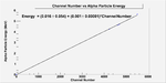
File:Raw data all.pdf
The main peaks are for the following channel numbers,
You need to redo these plots in publication quality with proper axis labels containing units.

| channel Number |
Energy Upper limit (MeV) |
Energy lower limit (MeV) |
average energy (MeV) |
Notes
|
| 4828 |
4.90 |
4.79 |
4.85 +_ 0.02 |
|
| 4869 |
4.94 |
4.83 |
4.88 +_ 0.02 |
|
Gamma Spectrum for U-233

Last runs
| Run Number |
start |
end |
Time (min) |
Shutter |
Source |
Count rate (counts/min) |
Notes
|
| 9005 |
05/15 15:00 |
05/16 10:55 |
|
open |
off |
50 |
|
| 9006 |
05/16 10:57 |
05/17 22:18 |
|
open |
on |
48 |
|
| 9007 |
05/17 22:23 |
05/18 19:20 |
|
closed |
on |
30 |
|
| 9008 |
05/18 21:46 |
05/19 19:59 |
|
closed |
off |
30 |
high beta effect
|
| 9010 |
05/21 23:23 |
05/22 10:00 |
|
closed |
off |
30 |
high beta effect
|
| 9023 |
05/26 13:06 |
05/26 13:17 |
11 |
open |
off |
87 |
GEM2.9kV 3.6kV
|
| 9024 |
05/26 13:20 |
05/26 13:27 |
7 |
closed |
off |
26 |
GEM2.8kV 3.5kV (beta effect decreased)
|
| 9032 |
06/13 12:35 |
06/13 12:45 |
10 |
open |
off |
87 |
GEM2.8kV 3.5kV (ISU power shutdown)
|
| 9033 |
06/13 12:35 |
06/13 12:45 |
10 |
closed |
off |
26 |
GEM2.8kV 3.5kV
|
| 9034 |
06/15 20:55 |
06/15 21:05 |
10 |
open |
off |
45 |
GEM2.8kV 3.5kV
|
| 9035 |
06/15 21:06 |
06/13 21:16 |
10 |
closed |
off |
27 |
GEM2.8kV 3.5kV
|
| 9036 |
06/17 14:48 |
06/17 14:58 |
10 |
closed |
off |
28 |
GEM2.8kV 3.5kV
|
| 9037 |
06/17 14:59 |
06/17 14:09 |
10 |
open |
off |
28 |
GEM2.8kV 3.5kV
|
The charge spectrum returned to were it was before the neutron exposure after 29 days for closed shutter.
QDC TDC PS-ADC setup
- Peak sensing gate
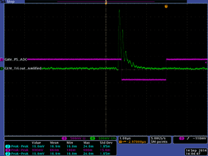
- QDC gate
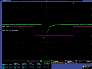
- TDC start
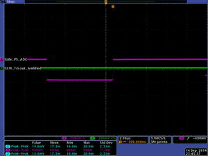
- TDC STOP
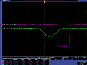
- QDC shows a difference
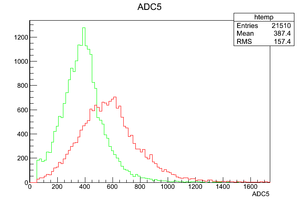
Measurements of the frequently used gas mixture 90/10 Ar/CO2 for the second peak
- Changes from the former set up
- Using the eG&G timing filter amp. 474 instead of the spectroscopic amp. to amplify the input for the peak sensing ADC.
- Gate of a width of 4us has been delyed to track the second peak, as a result part of output spectrum is lost except for the delayed part within the gate width as shown in the figures below:
- Lost
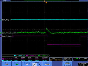
- Detected
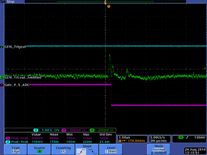
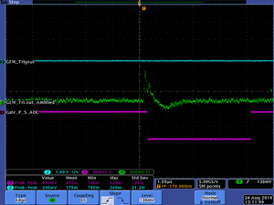
| Run Number |
Date |
start |
end |
Time (min) |
Shutter |
Source |
Count rate (counts/min) |
Notes
|
| 7435 |
08/24/14 |
19:30:48 |
19:55:32 |
|
open |
on |
400 |
a peak is noticed on channel 400
|
| 7436 |
08/24/14 |
19:59:05 |
20:40:11 |
|
open |
off |
216 |
the peak disappeared
|
| 7438 |
08/24/14 |
19:59:05 |
10:00:00 |
|
open |
on |
0.0146 |
triple coin., high noise, max. is ch 355
|
| 7444 |
08/25/14 |
21:17:25 |
21:20:35 |
|
open |
on |
230 |
gate delay 700 ns, peak disappeared 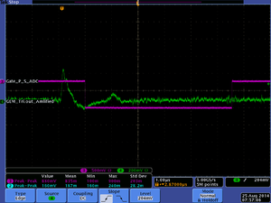
|
| 7446 |
08/25/14 |
21:29:51 |
21:38:55 |
|
open |
off |
185 |
does not count for P_B. peak disappeared
|
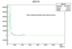
unknown gas mixed bottle measurements
- Updates
Changing the leading edge disc. to understand the Peak sensing and explain the cut int he peak sensing graph.
Measuring the noise. by starting by low signal rate to distinguish the signal from the noise.
- Channels and signals
| device |
ch |
input source
|
| ADC |
5 |
GEM's trigout
|
| Peak sensing 7 |
15 |
GEM's trigout
|
| Peak sensing 5 |
11 |
PMT Left
|
| Peak sensing 8 |
17 |
PMT right
|
| PS translator |
|
| TDC |
25 |
PMT L
|
| TDC |
27 |
GEM's trigout
|
| TDC |
29 |
PMT R
|
| TDC |
31 (Stopper) |
triple coincidence (OR Mode)
|
| CAEN N638
|
| TDC |
17 |
PMT L
|
| TDC B2 |
18 |
GEM's trigout multi-hit
|
| TDC B6 |
22 |
GEM's B_p
|
| TDC |
21 |
PMT R
|
| TDC 6 |
30 (pulser) |
triple coincidence (OR Mode)
|
| TDC 7 |
23 |
delayed GEM's trigout
|
| Run Number |
Date |
start |
end |
Time (min) |
Shutter |
Source |
Count rate (counts/min) |
Notes
|
| 7273 |
08/06/14 |
07:10:38 |
11:41:00 |
12502 |
open |
off |
67 |
0.1 flow rate
|
| 7274 |
08/06/14 |
11:49:35 |
18:15:01 |
23126 |
closed |
off |
39 |
0.1 flow rate
|
| 7275 |
08/06/14 |
20:37:07 |
09:10:10 |
|
closed |
off |
40 |
0.2 flow rate
|
| 7276 |
08/06/14 |
09:15:00 |
09:32:00 |
|
open |
off |
80 |
0.2 flow rate amplification increases from 50 to 100
|
| 7277 |
08/06/14 |
09:33:08 |
11:40:42 |
7654 |
open |
off |
81 |
0.2
|
| 7295 |
08/08/14 |
17:36:58 |
19:55:59 |
4741 |
closed |
off |
60 |
0.2
|
| 7296 |
08/08/14 |
22:28:01 |
23:43:14 |
|
closed |
off |
58 |
0.3
|
| 7297 |
08/08/14 |
23:48:14 |
12:08:00 |
37186 |
open |
off |
93 |
0.3
|
| 7298 |
08/09/14 |
00:16:14 |
06:08:03 |
21109 |
closed |
off |
56 |
0.3
|
| 7299 |
08/10/14 |
19:27:12 |
20:09:04 |
2152 |
closed |
on |
107 |
0.1
|
| 7300 |
08/10/14 |
20:11:30 |
20:46:29 |
2099 |
open |
on |
136 |
0.1
|
| 7302 |
08/11/14 |
06:53:14 |
07:22:45 |
1771 |
closed |
on |
114 |
0.2
|
| 7303 |
08/11/14 |
07:26:58 |
07:48:01 |
1263 |
open |
on |
167 |
0.2
|
| 7305 |
08/11/14 |
13:21:16 |
13:55:05 |
2029 |
open |
on |
178 |
0.3
|
| 7306 |
08/11/14 |
14:41:00 |
15:40:00 |
3540 |
closed |
on |
110 |
0.3
|
| 7307 |
08/14/14 |
08:14:15 |
08:20:39 |
384 |
closed |
off |
|
0.1 noise measurements (pulser only)
|
| 7308 |
08/14/14 |
08:22:43 |
08:29:23 |
|
open |
off |
1314 |
0.1 noise measurements (pulser only) same noise level as shutter closed (ch. 86) for Peak sensing ADC
|
| 7309 |
08/14/14 |
08:35:09 |
09:45:37 |
4229 |
open |
off |
|
0.1 flow rate was not exact, little less.
|
| 7310 |
08/14/14 |
09:46:12 |
11:18:39 |
5547 |
open |
off |
54 |
0.1 flow rate was not exact, little less.
|
| 7311 |
08/14/14 |
11:19:45 |
13:01:57 |
6132 |
open |
off |
52 |
0.1 flow rate was not exact, little less.
|
| 7312 |
08/14/14 |
13:10:50 |
14:28:07 |
4637 |
open |
off |
72 |
0.1 flow rate was not exact, little less.
|
| 7313 |
08/14/14 |
14:30:24 |
15:38: 48 |
4056 |
open |
off |
80 |
0.1 flow rate as is used to be
|
| 7314 |
08/14/14 |
15:41: 52 |
16:46:55 |
3897 |
open |
on |
147 |
0.1 flow rate as is used to be
|
| 7315 |
08/14/14 |
16:49: 59 |
19:14:30 |
8729 |
open |
on |
148 |
0.1 flow rate as is used to be
|
| 7316 |
08/14/14 |
19:18:43 |
22:14:07 |
10596 |
open |
on |
147 |
0.1 flow rate as is used to be
|
| 7317 |
08/14/14 |
22:18:24 |
10:18:52 |
43220 |
open |
on |
0.0095 |
0.1 flow rate, triple coincidence
|
| 7318 |
08/15/14 |
10:24:00 |
12:42:23 |
8303 |
open |
on |
147 |
0.1 flow rate
|
| 7319 |
08/15/14 |
12:46:14 |
15:46:09 |
10795 |
open |
on |
148 |
0.1 flow rate
|
| 7323 |
08/15-16/14 |
16:59:39 |
06:03:11 |
46970 |
open |
off |
0.0011 |
0.1 flow rate, triple coincidence
|
| 7329 |
08/16/14 |
07:06:32 |
10:35:35 |
12543 |
open |
off |
83 |
0.1 flow rate, PMT's charge is measured for L and R
|
| 7330 |
08/16/14 |
10:41:58 |
12:48:33 |
7595 |
open |
on |
146 |
0.1 flow rate
|
| 7331 |
08/16-17/14 |
12:52:07 |
06:45:03 |
64384 |
open |
off |
0.0016 |
0.1 flow rate, triple coincidence, coda counted 111 but the data file is empty!
|
| 7332 |
08/17/14 |
06:52:26 |
07:04:45 |
739 |
open |
on |
1367 |
0.1 flow rate noise measurements with the wave generator
|
| 7333 |
08/17/14 |
07:05:50 |
08:53:54 |
|
open |
on |
155 |
0.1 flow rate
|
| 7334 |
08/17/14 |
08:57:02 |
13:13:38 |
|
open |
off |
82 |
0.1 flow rate
|
| 7337 |
08/17/14 |
14:17:24 |
14:30:29 |
|
open |
on |
1400 |
0.1 flow rate, GEM 2.92 kV , CATH 3.47kV(+50V), noise measurements with the wave generator
|
| 7338 |
08/17/14 |
14:31:37 |
16:17:45 |
|
open |
on |
163 |
0.1 flow rate
|
| 7339 |
08/17/14 |
16:20:25 |
16:35:45 |
|
open |
off |
1368 |
0.1 flow rate, noise measurements with the wave generator
|
| 7340 |
08/17/14 |
16:37:01 |
20:33:04 |
|
open |
off |
95 |
0.1 flow rate
|
| 7341 |
08/17-18/14 |
20:40:16 |
06:18:43 |
|
open |
off |
0.0015 |
0.1 flow rate, triple coincidence
|
| 7342 |
08/18/14 |
06:25:44 |
06:37:43 |
|
open |
on |
1403 |
0.1 flow rate, noise measurements
|
| 7345 |
08/18/14 |
06:39:23 |
14:17:58 |
|
open |
on |
0.0128 |
0.1 flow rate, triple coincidence
|
| 7355 |
08/18/14 |
16:03:29 |
19:59:51 |
|
open |
off |
75 |
0.1 flow rate, EM 2.82 kV , CATH 3.37kV(-50V), CAEN translator is used
|
| 7356 |
08/18/14 |
20:03:05 |
20:07:58 |
|
open |
on |
2k |
0.1 flow rate, noise measurement
|
| 7357 |
08/18/14 |
20:08:43 |
22:48:22 |
|
open |
on |
142 |
0.1 flow rate
|
| 7358 |
08/18-19/14 |
22:53:13 |
10:52:44 |
|
open |
on |
0.0082 |
0.1 flow rate , triple coincidence
|
| 7359 |
08/19/14 |
10:55:49 |
10:59:52 |
|
open |
on |
2.1k |
0.1 flow rate , noise measurement
|
| 7360 |
08/19/14 |
11:00:38 |
14:26:38 |
|
open |
on |
156 |
0.1 flow rate noise measurement with 1 Hz sampling
|
| 7361 |
08/19/14 |
14:40:49 |
18:25:00 |
open |
on |
0 |
0.1 flow rate with 1 Hz sampling (AND gate)
|
| 7362 |
08/19/14 |
18:33:15 |
18:38:54 |
|
open |
on |
1.5k |
0.1 flow rate triple coinc.(OR)
|
| 7363 |
08/19-20/14 |
18:39:46 |
13:39:45 |
|
open |
on |
0.0081 |
0.1 flow rate triple coinc.(OR)
|
| 7364 |
08/20/14 |
13:44:56 |
13:50:57 |
|
open |
off |
1.55k |
0.1 flow rate noise measurements, 2.87, 3.42kV for GEM and CATH
|
| 7367 |
08/20/14 |
15:08:27 |
16:49:37 |
|
open |
off |
86 |
0.1 flow rate, 2.87, 3.42kV for GEM and CATH
|
| 7368 |
08/20/14 |
16:53:42 |
17:15:49 |
|
open |
on |
154 |
0.1 flow rate
|
| 7369 |
08/20/14 |
17:17:39 |
20:28:43 |
|
open |
off |
86 |
0.1 flow rate, spec. amplifier decreased from 100 to 50
|
| 7479 |
08/27/14 |
10:02:21 |
10:42:09 |
|
open |
on |
64 |
0.1 flow rate,
|
| 7480 |
08/27/14 |
10:46:18 |
14:17:22 |
|
open |
off |
11 |
0.1 flow rate,
|
| 7481 |
08/27/14 |
14:19:33 |
14:43:39 |
|
close |
on |
78 |
0.1 flow rate,
|
| 7488 |
08/27/14 |
16:16:37 |
16:48:53 |
|
open |
on |
86 |
0.1 flow rate,
|
| 7491 |
08/27/14 |
18:09:27 |
18:59:05 |
|
open |
on |
86 |
0.1 flow rate,
|
Peak sensing measurements by 08/28/14
Peak sensning measurements for GEM were recorded in the time between 8:00 am to 9:44am for shutter open as the following
| Source On |
Source Off
|
| 7507 |
7506
|
| 7509 |
7508
|
| 7511 |
7510
|
| 7513 |
7512
|
| 7515 |
7514
|
| 7517 |
7516
|
| 7519 |
7518
|
| 7521 |
7520
|
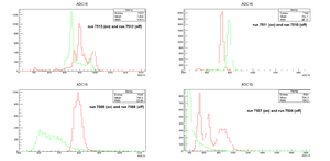
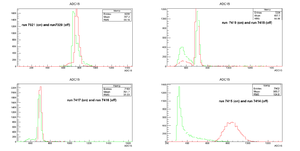
Different output for each run when Peak sensing is used to measure the charge, what is noticed that the charge is different from one run to another, but all the runs show that the amount of charge collected is bigger when the shutter is open with the source on it except for run 7511. By comparing all the runs, As the shutter is open, the maximum charge is collected by channel number 800, as the source is on the detector, the collected charge reached up to channel 1000 at most.
Measuring the data started by 8 am, the noise rate increased so it increased the event rate from 30s to 80s event/s, and it did not decrease until now (Thur. 15:36 08/28/14). all module wiring were checked but without any result. I am using the 90/10 Ar/CO2 bottle as hope to take some measurements but when the noise level goes down maybe this evening to repeat the same measuremnts.
The following reference shows a change in collected charge as the tenperature changes <ref>"Discrimination of nuclear recoils from alpha particles with superheated liquids" F Aubin et al 2008 New J. Phys. 10 103017 </ref>
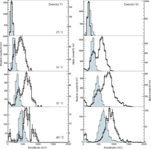
Flow rate and figures
- 03 flow rate
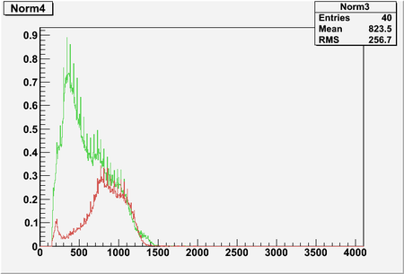
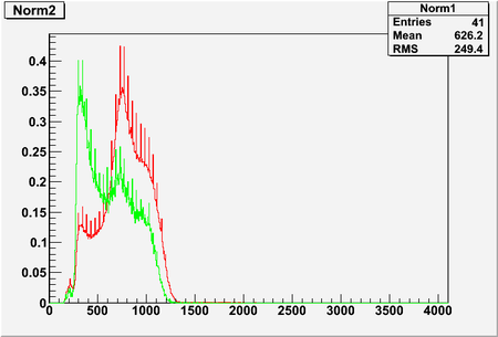
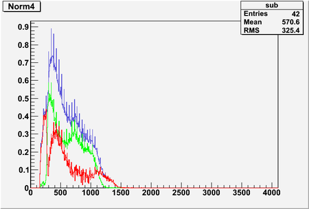
- 02 flow rate
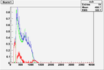
01 flow rate
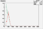
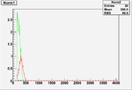
Common Start Common Stop exchange
Edit the file
cd /usr/local/coda/2.5/readoutlist/v1495trigPAT/
as the following:
for common start comment:
/* c775CommonStop(TDC_ID);
for common stop uncomment:
c775CommonStop(TDC_ID);
Ionization xsections for different particles emitted from U-233
- Photons
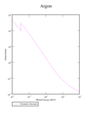
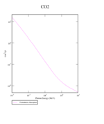
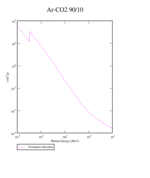
Ref. : http://physics.nist.gov/PhysRefData/Xcom/html/xcom1.html
- Electrons
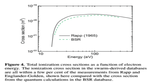
Ref. :
Data Nucl. Data Tables 54 (1993) 75 File:Electron ionization Ar.pdf
- Alpha Particles
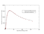
Ref. :
http://www.exphys.jku.at/Kshells/
Data Nucl. Data Tables 54 (1993) 75
Coincidence Measurements for GEM and the Plastic scintillator
- Coincidence Measurement for the scintillator PMT's without shielding and without source
| Date |
Time |
No. of Counts (counts) |
Count rate (counts/min)
|
| 07/09/14 |
1066 |
659005 |
618
|
| 07/10/14 |
538 |
368974 |
686
|
- Triple coincidence Measurement for the scintillator PMT's shielded and without source
Triple coincidence among the 2 PMT's and the GEM detector is measured using coincidence module caberra 2144 and ortec 778 counter, count rate is 0.3+_ 0.03 Hz. However, the rate was zero before shielding.
The following pics show The GEM output with triple coincidence signal, it is observed that different GEM peaks coincide with the triple signal, which shows that adding the shielding contaminates the neutron signal.
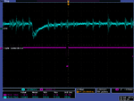
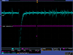
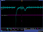
Coincidence Measurements for the Plastic scintillator after shielding
- Without source
The plastic scintillator count rate before shielding and without source was in average 12 +_ 1 Hz, lead is added to the GEM and to the plastic scintillator which did not change the rate of the coincidence for the plastic scintillator . Neither closing the box door with lead nor adding lead to the top of the box did make any change in the number of counts for the plastic scintillator.
- With a source
Background count rate
| Date |
Time |
PSD_e (counts) |
PSD_e (counts/min) |
LED (low disctrinimation)(counts) |
LED (low disctrinimation)(counts/min) |
LED (high disctrinimation) (counts) |
LED (high disctrinimation) (counts/min)
|
| 07/01/14 |
1166 |
56671 |
49 |
2936748 |
2519 |
10 |
0.009
|
| 07/01/14 |
231 |
10529 |
|
572657 |
|
1542 |
|
data graphs
- [math]S_{HLE}[/math]
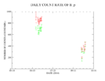
The above graph represents the change in the count rate of B_p, as the shutter is open (green) and as it is closed (red), the error bars get smaller since each point represents the average of two sets of daily measurements, in addition to, changing the PS discriminator's level after the second measurement.
- [math]S_{PSD}[/math]
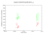
The above graph has the same legend as the one for B_p, error bars increase for some data when the shutter is open, since one or more of the daily measurements has a higher number of counts because of U-233(4)'s spentaneous fission. (the number of counts is close to the number of counts as the shutter is open and the source is on).
Small=[math]S_{PSD} - S_{PSDE}[/math]
Testing GEM Experiment test 10/23/13
The GEM detector was tested for signal and discharge as the voltage of the cathode and HV-circuit divider is 3.3 kV and 2.7 kV successively.
The GEM detector signal is observed as it used to work before. the pictures below show the signal detected as the shutter is open and as it is close.
| shutter close |
 |

|
| shutter open |
 |
 |
 |

|
THGEM#9 Counting Experiment test 1/4/13
THGEM#9 Counting Experiment
GEM HV-divider circuit
GEM HV-divider circuit in shown in the figure, measurements were recorded for for top and bottom voltage of each preamplifier.
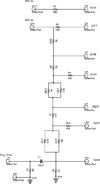
The table below shows value of the voltage on each preamplifier's side relative to ground.
| [math] V_{source} \pm 1 [/math] |
[math] V_{G1T} \pm 1 [/math] |
[math] V_{G1B} \pm 1 [/math] |
[math] \Delta V_1 \pm 1 [/math] |
[math] V_{G2T} \pm 1 [/math] |
[math] V_{G2B} \pm 1 [/math] |
[math] \Delta V_2 \pm 1[/math] |
[math] V_{G3T} \pm 1 [/math] |
[math] V_{G3B} \pm 1 [/math] |
[math] \Delta V_3 \pm 1 [/math]
|
| 2550 |
2579 |
2259 |
304 |
1671 |
1394 |
279 |
818 |
570 |
245
|
| 2600 |
2630 |
2303 |
310 |
1704 |
1421 |
285 |
834 |
581 |
250
|
| 2650 |
2680 |
2348 |
316 |
1737 |
1449 |
290 |
850 |
592 |
255
|
| 2700 |
2731 |
2393 |
322 |
1770 |
1476 |
296 |
866 |
603 |
260
|
| 2750 |
2781 |
2373 |
328 |
1803 |
1503 |
302 |
882 |
614 |
264
|
| 2800 |
2832 |
2482 |
332 |
1836 |
1530 |
307 |
898 |
625 |
269
|
The source voltage means the voltage value on the 4-channel CAEN N470 display. (suppose to be equal to the voltage of the top GEM1).
the values are going to be an input for ANSYS which is going to simulate the electric field for each source voltage separately, ANSYS' output files will be an input for Garfield to simulate the electron multiplication by the triple GEM.
GEM alpha-Beta detector counter
GEM Alpha-Beta detector counter
GEM gain data graphs and GEM Calibration in LDS
GEM Detector
GEM performance QDC data graphs
Calibrating GEM detector
Electronics Flow Chart
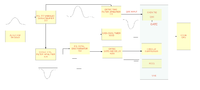
GEM Detector and Scintillator
GEM and Sci. data and measuurements
GEM gain data graphs and GEM Calibration at the IAC
Haitham may only alter the QDC's dual timer and a CFD for the QDC in the IAC DAQ.
Haitham may only add signals to the NIM->ECL translator
Haitham is not allowed to change any cables that are used for the PAA setup
- Summary
The detector is installed in the IAC after modifications took place in the detector design.
These modifications are:
1- The detector kipton window's area increased to the same size of the GEM cards( 10X10 cm)
2- The distance of the cathode from the first GEM increased up to 1.2 cm. previously the distance was about 3.5 mm. (No change in GEM's distances 2.8mm, or the readout 0.5 mm)
Increasing the drift distance demands an increase in cathode potential to maintain the same values of the electric field in the old setup.
3- The detector is installed in a wooden box, in addition to a plastic scintillator which was placed to cover part of the detector window.
GEM performance data graphs
Electronics Flow Chart
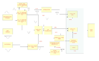
200px
U-233 fission x-section data and fission yield
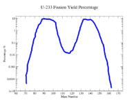
What is the energy distribution of Beta, Photon and alpha from U-233
Alpha
| nuclide |
Energy (MeV)
|
| Pb-213 |
8.4
|
| Bi-213 |
5.9
|
| At-217 |
6.3
|
| Fr-221 |
6.3
|
| Th-229 |
4.85 (alpha spectrum, highest counts for is 4.85 MeV)
|
Gamma
Gamma distribution for U-233 and its daughters are in metioned in details in the documents , File:U233 day gamma.pdf <ref>http://www.radiochemistry.org/periodictable/gamma_spectra , Wed. 04/10/2013</ref>
The energy range of the emitted gamma is shown in the following table .
| nuclide |
Energy Minimum |
Energy Maximum (keV)
|
| U-233 |
25 |
1,119
|
| Ra-225 |
40 |
40
|
| Ac-225 |
10.5 |
758.9
|
| Fr-221 |
96.8 |
410.7
|
| At-217 |
140 |
593.1
|
| Bi-213 |
323.81 |
1,119.4
|
Beta
Beta particles are emitted mainly from U-233 daughters as shown in the figure <ref> http://itu.jrc.ec.europa.eu/index.php?id=204, Wed. 04/10/2013 </ref>
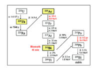
U-233 -> Th-229, emitted alpha particles have energy of 4.8 MeV.
Insert energy distribution for Betas
The following table shows the negative beta emitter nuclides,their parent nuclides, and their half lives:
| Nuclides |
energy (MeV) |
half life
|
| [math]Ra^{225} \rightarrow Ac^{225}[/math] |
0.357 |
14d.
|
| [math]Bi^{213} \rightarrow Po^{213}[/math] |
1.426 |
46min.
|
| [math]Tl^{209} \rightarrow Pb^{209}[/math] |
1.981 |
2.2 min.
|
| [math]Pb^{209} \rightarrow Bi^{209}[/math] |
0.644 |
3.25h
|
| [math]Bi^{209}[/math] |
1.893 |
stable
|
What is the energy distribution after the 1 mm FR4 shutter
electron shutter penetration
The energy distribution below represents the incidence electron on a 1 mm FR4 shutter.

graph of electron energy for electron penetrating shutter (did any not penetrate?, how many?)
photons below were produced by above incident electron?
The energy distribution of photons was observed on the opposite side of the shutter

Electrons (with least energy from U-233= 0.2 MeV) pass through the shutter have the energy distribution below.
alpha shutter penetration
photons
Number of ions produced from Beta and Photon in ArCo2
EMTest10 is used to calculate the average number of ions (electrons) when a 101 beta of 1 MeV are fired in a world that contains ArCO2. (13.5 per primary electron).

The needed time to observe the GEM signal
In the case of triple GEM detector with a gas flow of 0.3 SCFH and 2650V and 2950V on GEM cards and cathode successively, a signal lower than the noise (of 16 mV and amplified twice) is observed at 770.0s +/- 0.1.
The normal rate (8 MHz +/- 2 as measured by the oscilloscope) is observed after 952.9s +/- 0.1.
THGEM card tasks and tests
- New THGEM cards
Two new fully machined cards are going to be tested in air and ArCH4, if they passes 2000 V potential bwtween the top and the bottom, then they are going to be installed in ArCh4 gas chamber.
The older THGEM cards will have a high voltage enough to have one spark/min to clean impurities or surface defects.
GEM Signal after the latest modification on the fission chamber 07/01/13
The signal of the detector is observed as the shutter is open and close.
| shutter close |
 |
 |
 |

|
| shutter open |

|
GEM's signal testing when it a long cable is used
The GEM signal is tested when a long cable is used to transfer the signal to the oscilloscope as the shutter is open, and without the cable. Oscilloscope pictures shows an attenuation to the signal up to 30%.
| Long bnc cable |
 |

|
| Short bnc cable |

|
Roy's detector infomation and measurements
U-233 metal deposited source is measured by Protean Instrument corporation gaseous detector, has a model number of WPC9450 (serial number: 0915723)and uses (P10) gas mixture, as shown below:
| Shutter position |
Alpha particles /min. |
Beta particles /min.
|
| Open |
6879 |
900
|
| Close |
1 |
38
|
The source was in a plate of a diameter of 16 cm which was exposed to to the sensitive part of the detector of a height of 2-3 mm.
The activity of the source is calculated based on the solid angle [math] \frac {A \times W}{4\pi} [/math]
where A is the count per second
and W is the detector solid angle.
For the previous measurement, the solid angle is almost [math]2\pi [/math], so the the actvity of the source is twice the measured value in count/second.
IAC experiment producing neutrons
One of the IAC experiments produces neutrons, the neutron spectrum from Tungsten target is simulated outside and inside water (moderator) as shown in the figure below

In the simulation above , They are interested in close distances to the Tungsten target inside the water container, it is 1 ft cubed container and is made of aluminium and covered polyester.

References
THGEM design
THGEM#9
Media:Shalem_MSthesis_march2005.pdf
Media:Raz_Alon_MSthesis_Dec2007.pdf
Electric field Simulation
- Rim size dependence
File:THGEM Efield simulation.pdf
- 2010 THGEM design(s)
File:THGEM 2009 design gas efficiency.pdf
Simulations_of_Particle_Interactions_with_Matter
Voss and 3 russian references for Dy(n,x) cross sections
http://arxiv.org/abs/0903.3819 Dy photon gammas spectrum
http://www.ippe.obninsk.ru/podr/cjd/kobra13.php?SubentID=30974002
http://www.americanelements.com/thoxst.html
http://arxiv.org/pdf/physics/0404119
NIM_A535_2004_93[1]
File:NIM A590 2008 pg134 Eberhardt.pdf Prep Targets
Neutron cross sections for different elements Media:Neutron_cross_sections.pdf
http://www-nds.iaea.org/RIPL-2/
Media:n gamma cross sections at 25 keV.jpg
Media:n alpha cross section at 14.2 MeV.jpg
Media:ne cross section at 14 MeV.jpg
Media:high enegy fission x-section.jpg
Media:N_gamma_x-section_at_400_keV.jpg
Media:x-sections of reactions at 14 MeV.jpg
Media:n p x-section at 14.3MeV.jpg
Media: n gamma x-section at 14.5 MeV.jpg
Media: elastic x-section at 0.5 MeV.jpg
Media: n gamma x-section at 1 MeV.jpg
Media: n 2n x-section at 14.3 MeV.jpg
Donald James Hughes, Neutron cross sections, 2nd edition 1958, u.s.a atomic energy commission.Media:Neutron cross sections.pdf
File:NSAE 151 2005 319-334 Y.D. Lee.pdf
TGEM-2009 File:TGEM 2009.pdf
12 Volt power supply system.
http://www.lnf.infn.it/esperimenti/imagem/doc/NIMA_46128.pdf
http://electrontube.com.Media: rp097mono HV divier.pdf
http://www.cerac.com/pubs/proddata/thf4.htm#anchor550078
http://en.wikipedia.org/wiki/PC_board
http://wikipedia.org
A : concise review on THGEM detectors A.Breskin, R. Alon, M. Cortesi, R. Chechik, J. Miyamoto, V. Dangendorf, J. Maia, J. M. F. Dos Santos
GEANT4_Paticles_Models[2]
Resistors online store : http://www.justradios.com/rescart.html
RETGEMs
Media:Jinst8_02_p02012_THGEM_spark.pdf
Media:2010_INST_5_P03002.pdf
- Thick GEM COBRA
Media:THGEM_COBRA_08_10.pdf
Media: Nucl_Phys_B_Bidault_ novel UV photon detector.pdf
Media:Mauro micro pattern gaseuos detectors.pdf
Media:Development and First Tests of GEM-Like Detectors With Resistive Electrodes.pdf
http://www.supplydivision.co.uk/genitem.htm
http://www.radioshack.com/search/index.jsp?kwCatId=&kw=24%20gauge%20wires&origkw=24%20gauge%20wires&sr=1
Thick_GEM_versus_thin_GEM_in_two_phase_argon_avalanche_detectors (HV circuit)[3]
Stainless Steel deflection [4]
Data Sheets
radioactive surface cleaner NoCount MDSD File:Radioactive surface cleaner.pdf.
Th-Xsection references
File:Th-232 fxsection Behrens 0.7-1.4MeV.pdf
File:Th-232 fxsection Blons 1975 1.2-1.8MeV.pdf
File:Th-232 fxsection ermagambetov 0-3MeV.pdf
File:Th-232 fxsection Henkel 0-9MeV.pdf
File:Th-232 fxsection Ohsawa original.pdf
File:Th-232 fxsection pankratov 3-35MeV.pdf
File:Th-232 fxsection protopopov distancefromthesource.pdf
File:Th-232 fxsection rago 12.5-18MeV.pdf
U-238-Xsection and coating references
relative cross section and calibration samples characteristics for a well determined number of fissions per second
File:Eismont relative absolute nf induced intermediate energy.pdf
- U_238 cross section error analysis
INTERNATIONAL EVALUATION OF NEUTRON CROSS-SECTION STANDARDS, INTERNATIONAL ATOMIC ENERGY AGENCY,VIENNA, 2007 File:U238-xsection.pdf
U_238 (0.5-4MeV) and Th_232 (1-6MeV) fission cross section with statistical error.File:Th-232 U238 xsetion data ebars.txt
File:Pankratov fxsection Th232 U233 U235 Np237 U238 5-37MeV.pdf
Thorium Coating
ThF4 target for sputtering coatings
http://www.cerac.com/pubs/proddata/thf4.htm
Machining Uranium
Uranium will ignite in powder form
http://www.springerlink.com/content/rr072r52163x0833/
- coating Uranium
[[5]]
http://cat.inist.fr/?aModele=afficheN&cpsidt=16864172
Calorimeters/Detectors:
DU sheet is in wide-scale use as an absorber material in high-energy physics research at large accelerator laboratories. The high atomic number and density of DU presents a large number of atoms per unit volume to interact with the particles emerging from collisions in these detectors. Also the slight background radiation from DU enables in situ calibration of the electronic read out devices within such detectors, thereby improving the accuracy of measurement.
http://www.2spi.com/catalog/chem/depleted-uranium-products.html
[6]
[7]
- IAEA Photonuclear Data Library [8]
- Data Acquisition
Warren_logbook[9]
Warren_Thesis [10]
Related To Gaseous Detectors
Breakdown and Detector Failure (10/21/10)
- Different kind of micro-pattern detectors
- References
1- A. Bressan, M. Hocha : NIM A 424 (1999) 321—342 File:High rate behavior and discharge limits in micro-pattern detectors .pdf
2- Fonte and Peskov IEEE 1999 :File:Fundamental limitations of high rate gaseous detectors.pdf
3- B. Schmidt: NIM A 419 (1998) 230—238 File:Microstrip gas chambers Recent developments radiation damage.pdf
Ideas
1.) Can we mix resistive paste (Encre MINICO) with TH-232. We construct a "bed of nails" to place a predrilled G-10 board with a copper border. The nails fill in the holes of the G-10 to keep the paste out. Ecre MINICO is a resistive paste used for transistors.
a.) Get some resistive paste.
http://www.leggesystems.com/p-253-elimstat-uxm-ccp.aspx
Resistive glue to compare
File:Duralco 4461.pdf
http://www.ellsworth.com/conformal.html?tab=Products
http://www.ellsworth.com/display/productdetail.html?productid=764&Tab=Products
http://www.ellsworth.com/display/productdetail.html?productid=2067&Tab=Products
http://www.cotronics.com/vo/cotr/ea_electricalresistant.htm
b.) mix with a metal similar to Th-232.
c.) construct bed of 0.4 mm nails. Look for 0.4 mm diameter pins.
7/31/2009
New vendor for carbon paste.
http://www.electrapolymers.com/productItem.asp?id=33
The data sheet does not show any information about the thickness of the paste.
The company has a distributor in the usa (877)-867-9668. A phone call is expected on Sat. 8/3/2009 about the availability of the product.
TGEM Mask Design
Coating U-238 or Th-232 is essential for neutron detection in the range 2-14 MeV, but THGEM contains holes that should be protected from any coating material. So, a mask is designed to cover these holes. The holes are in drilled to be on the corners of hexagonal of 1mm side length as in the figure:
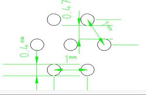
The mask is made of stainless steel, 10 um laser tolerance with cut the plate to get the shape in the figure:
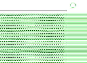
Please look at the following files for more details:
Make number bold black font. Add color so it is clear that they are holes in a material.
File:Copper foil 04mm.pdf
File:Holes mask together.pdf
TGEM_Mask_Design
P_D
Performance of THGEM as a Neutron Detector
H_Proposal_Defense
Vendor
Thick Film Screen Printers
http://www.sciquip.com/browses/browse_Cat.asp?Category=Screen+Printers
http://www.marubeni-sunnyvale.com/screen_printing.html
Go Back TGEMS
tektronix oscilloscope
134.50.3.73
http://134.50.203.63/
<references/>


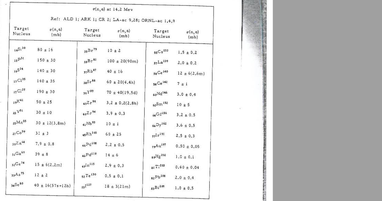
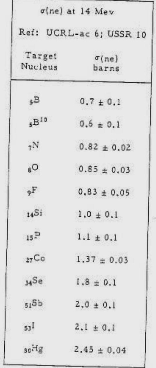
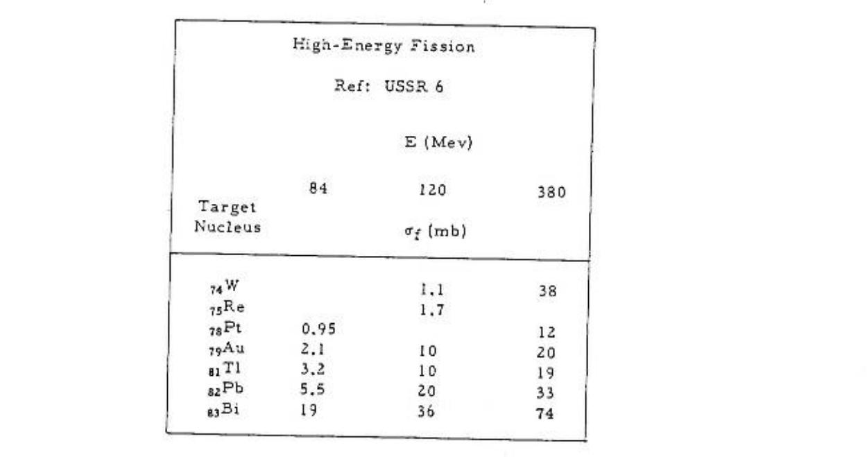
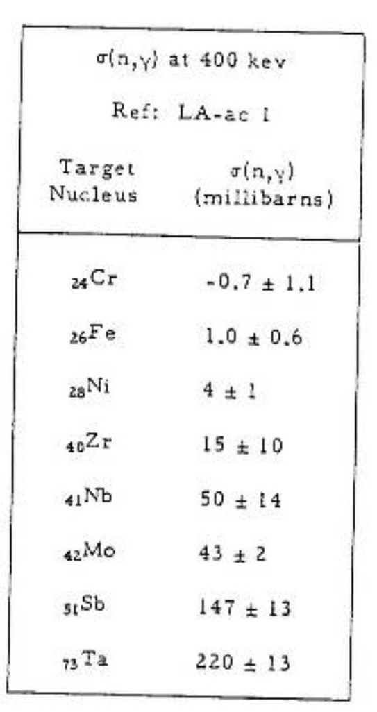
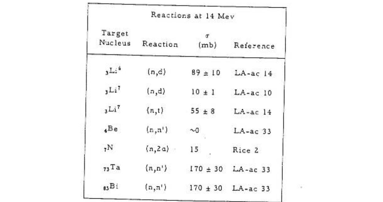
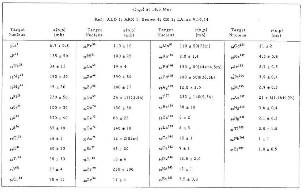
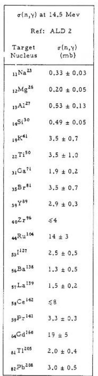
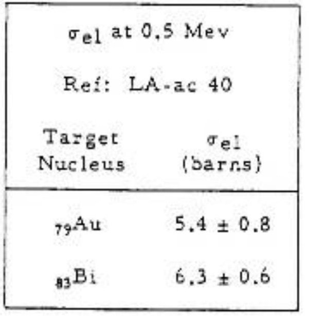
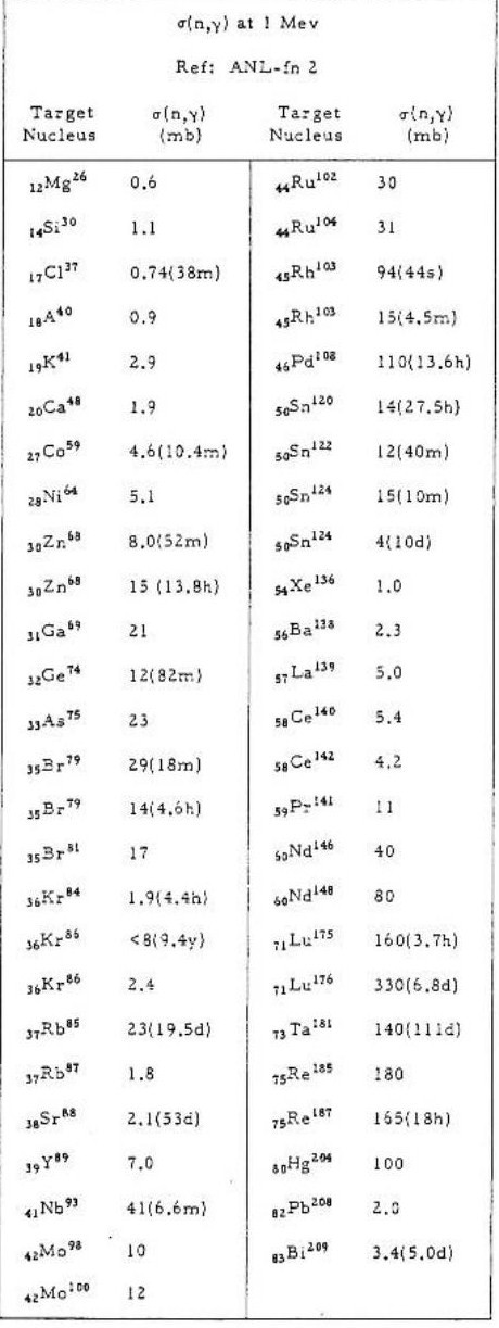
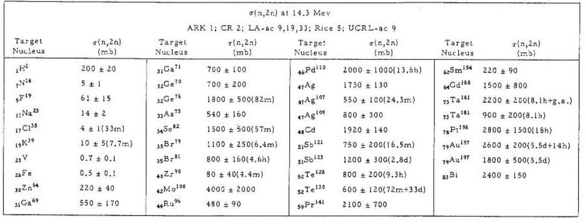

