GEM Alpha-Beta detector counter
GEM before modification
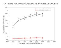
GEM detector was operated without U-233 source inside the chamber, the detector's counting rate relationship with the applied voltage on the cathode was investigated and the result is shown by the following figure:
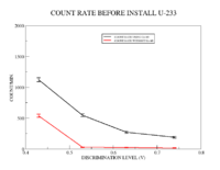
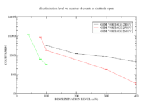
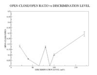
In the counting experiment, P.S. discriminator was used to discriminate againt the noise, the relationship between the count rate and the discrimination level (without changing the applied voltages on GEM cards and the cathode. The data is represented by the following figure:
The detector signal detected when the voltage on GEM HV-circuit was 2800V, but it was lower the noise, but raising up the voltage to 3000 V made the signal higher than the noise. So all the previous measurements observed ast he GEM HV-circuit was 3000V.
GEM after modification
A new cathode with thin layer of U-233 and its a FR4 shutter were added to the chamber, the distance of cathode is 8mm from the first GEM card, the distances between the GEM cards have equal distances to the ones before the modifications.
The VFAT connectors are connected together to provide the signal of the signal of the readout plate.
A signal is observed (on trigout and readout)as the voltage magnitude on the GEM HV-voltage circuit is 2800V, and the cathode is 3100V.
Prelimanry count rate measurements were recorded using 474 time filter amplifier, P.S. 710 discrimonator (at 0.7V) and a counter in the following table:
| Shutter location | Counts/min | |
|---|---|---|
| close | 2049 | 2500 |
| open | 6561 | 6360 |
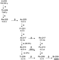
The high rate of counts observed as the sutter is close is due to the U-233 beta decay as shown in the figure:
Shutter Open/Closed Scope pictures
Insert Scope pictures for shutter Open and Shutter Closed (use integration mode of scope to measure the pulse area in units of V*ns)
Calculate the charge in each pulse
Two Counter Counting Experiment
Two counters were used for counting the detector signal after installing U-233 inside the detector. The signal detected by the trigout was an input for P.S. eight channel variable gain amplifier (model 777) that had two outputs fed two types discriminators; EG&G-EN CF4000 Constant Fraction Discriminator and P.S. octal leading edge discriminator (model 710). The discrimination level of each of them allowed one of the counters (ortec 875) to count for all the amplified signal pulses produced as the shutter was close, simultaneously, the second counter to count for them as the shutter was open. (The CFD D.V. was 0.025V and 6x 474 Ortec TFA , LED D.V. was 1.52V and 1x TFA)
Due to the lower pulse amplitude for the alpha particles the higher one for negative beta, decrease the detector gain may help in counting for alphas and fission fragments without counting for beta particles. Or we can use Ortec 552 (pulse shape analyzer and timer) with ortec 460 (delay shaping line amplifier).
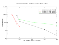
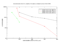
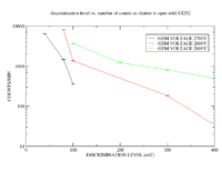
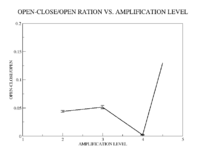
Counting started by the lowest voltage alpha signal is observed (2.6 kV, 2.9 kV), an ortec 474 is used and it amplifies the signal up to 6x.A leading edge P.S. 710 octal discriminator is used with a discrimination level of 150 mV.
- Without a source
- With a source
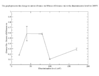
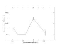
Shutter Open (Source on - Source off)/Source on vs. discrimination level
The uncertainty is calculated as the following:
u=on v=off
Go back [1]
