Difference between revisions of "Neutron TGEM Detector Abdel"
| Line 214: | Line 214: | ||
* The distance is increased to about 1 mm, the detector is tested again and we hit 6.3 kV as maximum voltage on the THGEM without the cathode. | * The distance is increased to about 1 mm, the detector is tested again and we hit 6.3 kV as maximum voltage on the THGEM without the cathode. | ||
| − | + | =4/14/11= | |
* The distance between the THGEM is increased to another 1mm ( to have a total of 0.5 cm), the cathode is added to the group with a maximum distance from the top THGEM card, observation will uploaded as soon as possible. | * The distance between the THGEM is increased to another 1mm ( to have a total of 0.5 cm), the cathode is added to the group with a maximum distance from the top THGEM card, observation will uploaded as soon as possible. | ||
Revision as of 16:08, 14 April 2011
AFCRD Reports-2011
- A vendor is being sought for a flex circuit version of the readout card adapter in order to allow the readout cards to attach to the detector more easily.
- A detector gas system upgrade is underway and should be completed before the next quarter
- A new TGEM card has been machined which was redesigned to reduce spark discharge between two adjacent TGEM preamplifier cards previously observed at 1.7 kV. The expectation is to reach a TGEM voltage of 2 kV with two preamplifier cards stacked on top of each other and separated by 2.5 mm.
January
- Determined the closest distance between two TGEM amplifier cards at 2kV to be 2.5 cm.
- Readout card adapters have arrived
- A third TGEM amplifier has been fabricated
February
- A third THGEM card is installed, the detector is ready to test with cosmic rays.
- New flex circuit adapter cards have been stuffed with connectors. The 16 signals on five 20 pin connectors will be merged onto one 130 connector used by the digitization cards.
- New HV-circuit design is ready to give the needed voltage to operate three THGEM cards simultaneously with the cathode.
- A gas system is currently in place with a 50 micron filter and a flow meter. Check valves are being sought to support a system using 2 supply tanks for continuous operation. The check valves will allow an empty tank to be replaced while the gas system continues operating on a second tank.
Look for NE213 and NE230 liquid scintillator detectors for fast neutrons. Does the neutron leave the detector?
March
- The detector's cathode-TGEM distance had to be increased in order to avoid a spark discharge problem was found when testing the detector at HV using cosmic rays.
- A modification took place on the detector's cavity by raising up the detector's widow 5 cm which helped to increase the distance between the cards.
1/13/11
- Sparking Test
Sparking test for the HT-THGEM of holes size(76) and rim (63)
| Separation distance (mm) | type of gas surrounding | V1GB (kV) | V1GT(kV) | V2GB (kV) | V2GT (kV) | Notes |
| 6.5 | Ar/CO2 | 0 | ||||
| 5.0 | Ar/CO2 | 0 | ||||
| 2.6 | Ar/CO2 | 0 | -2 | +2 | -3 | sparking on the edge then holes starts to spark too |
| 2.6 | Air/CO2 | 0 | -2 | -2 | 0 | no sparking. |
where:
V1GB = bottom of the first THGEM card which is placed 2 mm above the charge collector
V1GT = top of the first THGEM card
V2GB = bottom of second THGEM card just above the first TGEM card.
V2GT = top of second THGEM card.

1/21/11
- The THGEM card is still sparking because of the hook up wires; which are tested up to 600V by the manufacturer.
The maximum voltage applied for one card only is 2000V on the top and 2000V on the bottom of the card. As soon as the voltage increases more than 2000V on the bottom of the card. a spark is seen in the hole that contains the hook up wire. There is an insulation problem may get serious specially if we still planning to apply 4kV and 6kV on the THGEM card.
The following website is offering hook up wires solid core and can hold up to 2000V, 24 gauge size.
http://caledonian-cables.com/product/Hoop-Up_Wire/UL_1430_Hoop-Up_Wire.htm
we may use the wires supported by the glu to have a good insulation.
- Next step is to repeat the experiment again but after adding the glu on the soldered parts.
2/14/11
- Leakage current test
On Thur. 2/10 the leakage current measured for the max. voltage (around 300V) was in 25 nA using user1 setup.
Today the measured current for the voltages shown in the table using user0 setup in clean environment:
| Source Voltage(V) | GEM Voltage (V) | Current (uA) | Notes |
| 500 | 196 | 6.1 | Sparking rate was high in the beginning, higher current observed in a higher sparking rate |
| 570 | 224 | 23 | GEM sparking rate decreased after a while, current most of the time in the range of the noise level |
Switching to user1 setup when the voltage applied 224V on GEM foil, the maximum current measured was around 10um. The result is not enough to compare the accuracy of the two setups, but it gives a feeling that user1 setup is underestimating.
- The 3rd THGEM card is ready to pick up, the vendor suggested to find another place to do the one with massive number of holes since this semester there is not any time available to do it.
I will start working to collect the 3 cards together using the high voltage circuit distribution, an adjust is going to take place to get the desired voltage for the 3 cards in addition to the cathode.
2/15/11
The following figure shows the elastic xsection and fission xsection for U-238:

The elastic scattering is higher over the energy range of 5-14 MeV, the probability for the U-238 to recoil is higher than that to have a fission.
2/17/11
- The high voltage circuit is ready to get a voltage up to 9 kV from the source to provide a voltage up to 2 kV for each THGEM card and potential difference between successive cards up to 115 V (between the high voltage sides) and 80 V (between successive low voltage sides).
2/22/11

The operating voltage for the HV-circuit is 5kV, the voltages on the sides of the THGEM cards is as the following:
| Source Voltage(kV) | THGEM_T1 (kV) | THGEM_B1 (kV)Current (uA) | THGEM_T2 (kV)Notes | THGEM_B2 (kV) | THGEM_T3 (kV) | THGEM_B3 (kV) |
| 5.15 | 5.15 | 2.92 | 5.00 | 2.88 | 2.49 | 1.90 |
But in the case of connecting the two circuits together, the effect of the capacitor extends to the other circuit causing the difference in voltage between top and bottom of each THGEM cards is only 0.5kV.
3/10/11
- New design for HV-circuit
A new design is ready to feed the THGEM cards with voltage difference up to 2kV between the top and the bottom side of the card. Also source drops gradually according to that difference from 6 kV (operating voltage) to 0.1 on the bottom of the card which is closer to the read out card.
The follwing table shows the voltage distribution to the cards as the voltage source rises from 4 kV up to 6.5 kV.
| Voltage source (kV)+_ 0.01 | THEGM card number | Top side voltage(kV)+_ 0.01 | Bottom side voltage (kV)+_ 0.01 | Voltage difference between the two sides (kV)+_ 0.01 |
| 4.06 | 1 | 4.06 | 2.85 | 1.21 |
| 2 | 2.36 | 1.44 | 0.92 | |
| 3 | 1.38 | 0.08 | 1.3 | |
| 4.50 | 1 | 4.50 | 3.15 | 1.35 |
| 2 | 2.71 | 1.58 | 1.13 | |
| 3 | 1.54 | 0.08 | 1.46 | |
| 5.00 | 1 | 5.00 | 3.55 | 1.45 |
| 2 | 3.06 | 1.86 | 1.2 | |
| 3 | 1.80 | 0.11 | 1.69 | |
| 5.50 | 1 | 5.50 | 3.81 | 1.69 |
| 2 | 3.74 | 2.04 | 1.78 | |
| 3 | 1.98 | 0.12 | 1.86 | |
| 6.02 | 1 | 6.02 | 4.13 | 1.89 |
| 2 | 3.92 | 2.20 | 1.72 | |
| 3 | 2.15 | 0.13 | 2.02 | |
| 6.52 | 1 | 6.52 | 4.47 | 2.05 |
| 2 | 4.28 | 2.39 | 2.11 | |
| 3 | 2.33 | 0.14 | 2.15 |
THGEM card number 1 is the closest to the cathode. THGEM card number 3 is the closest to the readout card.

3/18/11
- Sparking Cathode
The cathode is still sparking even when it is replaced by another new one with the same dimension and distance from the THGEM cards. when I tried to make a little higher I could not since the top part of the detector has less space to get the increment in height.
Machining the top part is important to get more distance for the cathode to avoid the sparking (minimum another 2 cm and if it is more it would be better).
if we succeed to get that space, then a longer corner screw can be installed to give us a little flexibility to get a better distance for the cathode as it is mounted vertically.
4/4/11
- The detector window's extension is completed and it is test, totally sealed without any gas leakage.

4/9/11
- The THGEM is tested to look for a signal, Na-22 and Co-60 sources were used for this purpose, the result that New kind of peaks were detected followed by a tail. Unfortunately the test did not reach the full voltage capacity (up to 6.5 kV) but it was operating under 4.5 kV.
- The detector was tested again before removing the cards without Ar/CO2 gas, the applied voltage on the cards was up to 2.5-2.7 kV, without any sparking, cathode was under 8 kV, without any sparks, I excluded the distance between the cards is small to cause a spark, otherwise I won't be able to reach that high voltage without any sparks.
- The detector was inspected after the test, signs of sparking were very clear on the THGEM, and they all located in the same side for the 3 cards but in different degrees of burns (the bottom one was he worst). Through the inspection I was wondering how can they all be burnt on the same side of the card ?????
4/13/11
- The detector was tested without the cathode, the maximum voltage was 6 kV without sparking, looks the distance should be increased to exclude it of being a reason for sparking and to hit 6.5 kV easily.
- The distance is increased to about 1 mm, the detector is tested again and we hit 6.3 kV as maximum voltage on the THGEM without the cathode.
4/14/11
- The distance between the THGEM is increased to another 1mm ( to have a total of 0.5 cm), the cathode is added to the group with a maximum distance from the top THGEM card, observation will uploaded as soon as possible.
Comparison ENDF evaluation of U-238 neutron fission xsection and GEANT4
 |
 |

|
INTERNATIONAL EVALUATION OF NEUTRON CROSS-SECTION STANDARDS, INTERNATIONAL ATOMIC ENERGY AGENCY,VIENNA, 2007 File:U238-xsection.pdf
- absolute f_xsection in the table 7.1 p.91
| Ref. number | inxn | data description | author | citation | notes |
| 809 | 238U(n,f) | Absolute | G. Winkler et al. | 91Jülich (1991) 514 | the paper represents f_xsection ratio measurements of U_238 to Al_27, Na_24, Fe_56, Mn_56 * found in library QC770 N742 1992) |
| 810 | 238U(n,f) | Absolute | K. Merla et al. | 91Jülich (1991) 510 | * The paper represents f_xsection ratio measurements of U_238, U_235 , Np_237, and Pu_239 for 4.45 MeV, 8.46 MeV, 18.8 MeV * very accurate description for the experiment details and through the figures and the tables * found in library QC770 N742 1992) |
| 877 | 238U(n,f) | Absolute | I.M. Kuks et al. | At. Energy 30 (1971) 55 | *measured f_xsection U_238 fission for 2.5 MeV Neutrons |
| 860 | 238U(n,f) | Absolute | N.N. Flerov et al. | At. Energy 5 (1958) 657 | *title : antinutrino , Mean number of neutrons emitted in fission of U235 and U238 by 14-Mev neutrons, Mean number of neutrons emitted in fission of U235 and U238 by 14-Mev neutrons |
Done In April (edited by 04/30/10)
1.)Testing the new laminate with random holes after applying the resistive paste on both sides. Also, the trial of applying the paste was done, 0.1 inch brush is used for that to avoid covering the holes with the paste. the following procedure were taken:
a- Voltage is applied on the the foil to check the first sparking place.
b- Applying the paste carefully on the area between the holes with very small quantities.
- Result
a) Applying the paste shifts the sparking area to next neighboring one, so looks this will lead us to cover all the areas between the holes to kill the sparks.
b)A need to keep the foil under voltage to keep tracking of the sparks which lead unfortunately led to loss the voltage between the two copper layers.
Even a drop of paste got stuck in one of the holes(which has low possibility since I cleaned all the paste applied very well), or the two layers are no longer isolated from each other!
2.)Final touches on the HV-circuit are done, diagrams are done by eagle with Gerber files, the chamber is ready for redesigning.
3.)Running Th-232 fission simulation without ionization on inca and daq1. Energies 1-9MeV (inca) and 19-22 MeV(daq1) will be done by today(04/30/10).
4.)Tracking the process to get Th-232, contacting other vendors for radioactive isotopes, trying to get low cost ones.
Th-232 and U-238 Activity in mCi
General information:
| Physical properties | U-238 | Th-232 |
| Half life in years | 4.468 X 10^9 | 1.405 X 10^10 |
| Decay rate per second | 4.91 X 10^-18 | 1.56 X 10^ -18 |
| Molar Mass g/mol | 238.02891 | 232.0381 |
| Activity of 2 kg in mCi | 0.68 | 0.22 |
Avogadro's number is 6.0221 X 10^23 /mol
1 Ci = 3.7 X 10^10 disintegration/ second
References
- 2010 THGEM design(s)
File:THGEM 2009 design gas efficiency.pdf
Simulations_of_Particle_Interactions_with_Matter
Voss and 3 russian references for Dy(n,x) cross sections
Media:Shalem_MSthesis_march2005.pdf
http://arxiv.org/abs/0903.3819 Dy photon gammas spectrum
http://www.ippe.obninsk.ru/podr/cjd/kobra13.php?SubentID=30974002
http://www.americanelements.com/thoxst.html
http://arxiv.org/pdf/physics/0404119
NIM_A535_2004_93[1]
File:NIM A590 2008 pg134 Eberhardt.pdf Prep Targets
Neutron cross sections for different elements Media:Neutron_cross_sections.pdf
http://www-nds.iaea.org/RIPL-2/
Media:n gamma cross sections at 25 keV.jpg
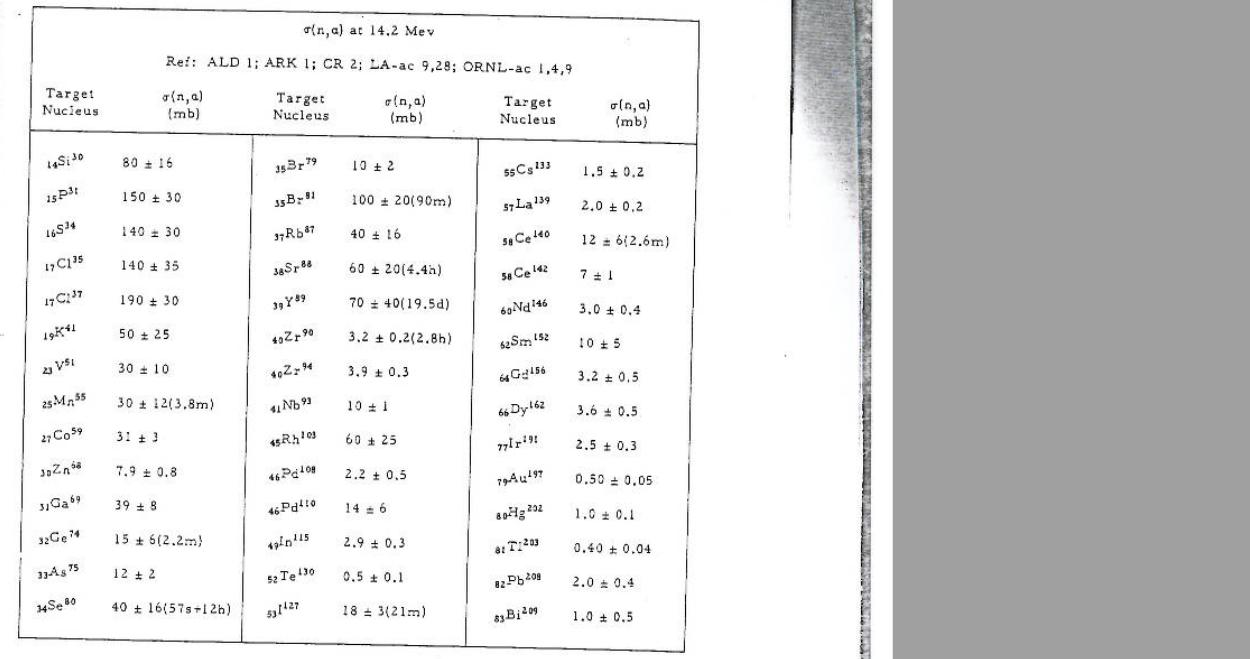
Media:n alpha cross section at 14.2 MeV.jpg
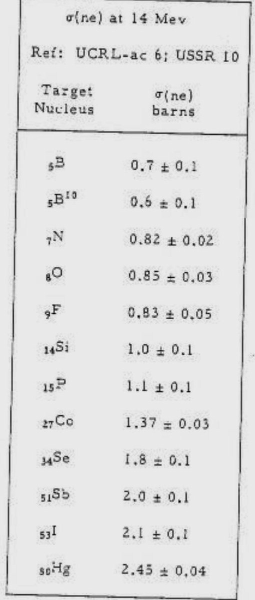
Media:ne cross section at 14 MeV.jpg
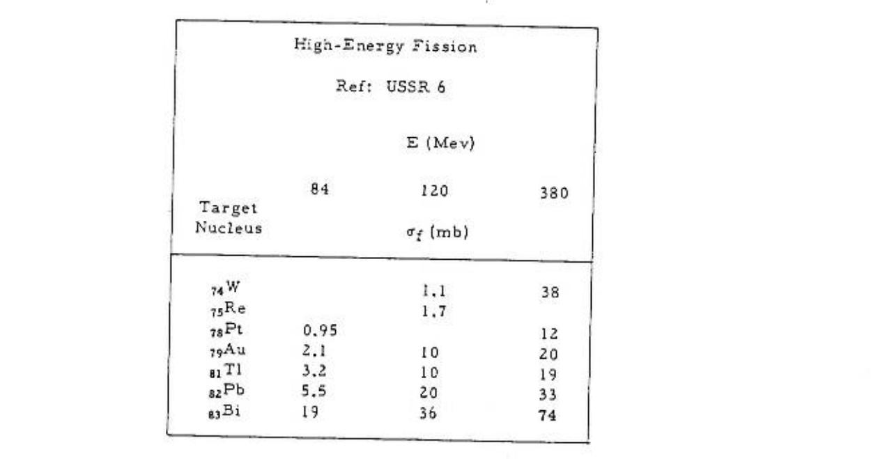
Media:high enegy fission x-section.jpg
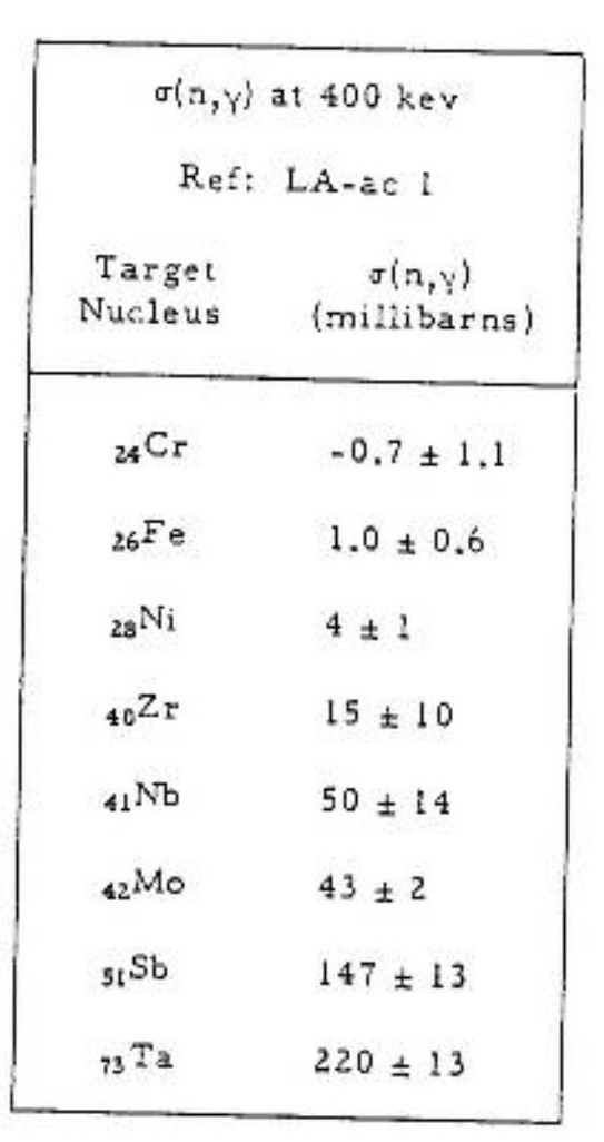
Media:N_gamma_x-section_at_400_keV.jpg
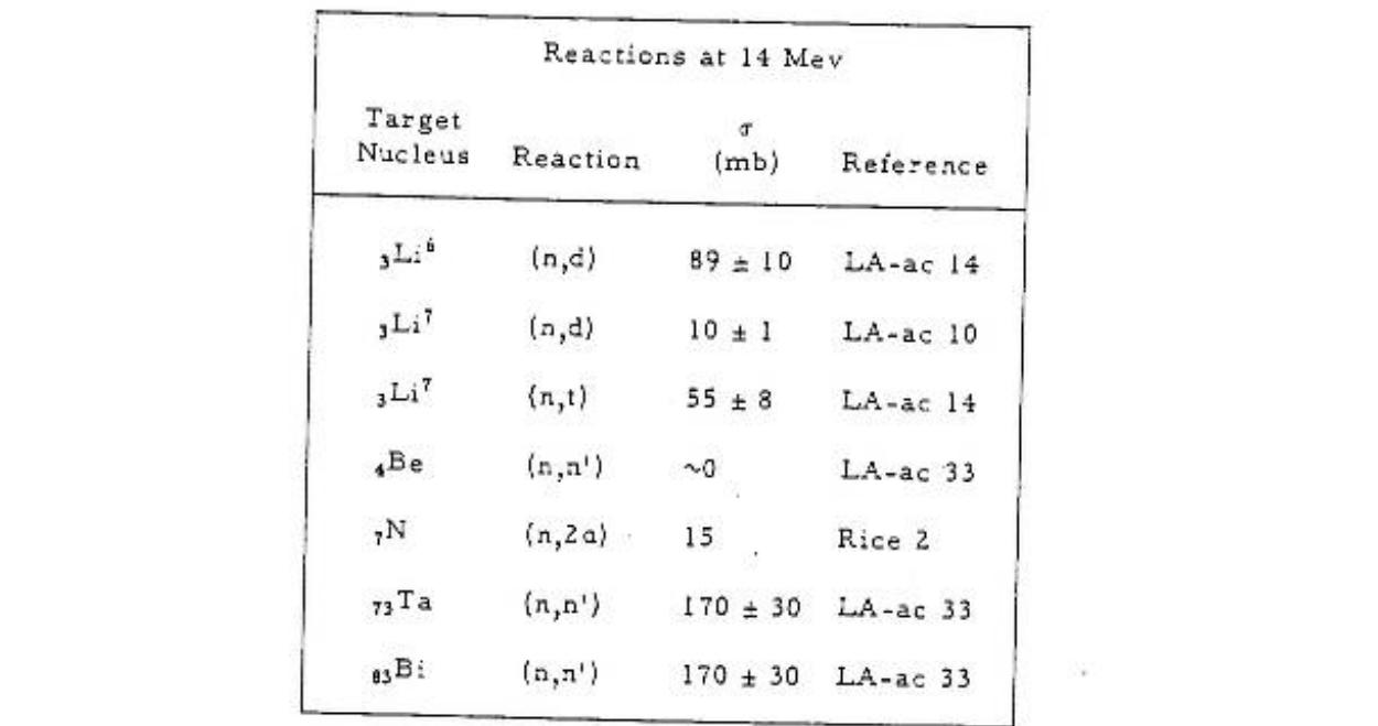
Media:x-sections of reactions at 14 MeV.jpg
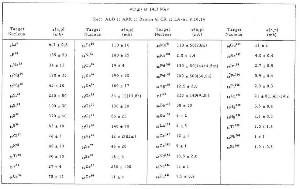
Media:n p x-section at 14.3MeV.jpg
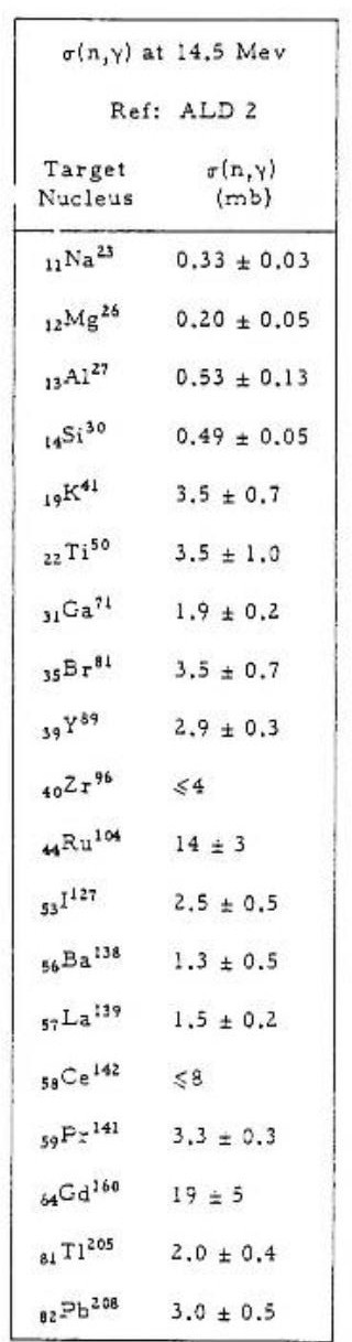
Media: n gamma x-section at 14.5 MeV.jpg
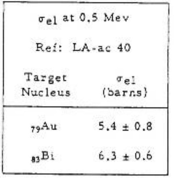
Media: elastic x-section at 0.5 MeV.jpg
Media: n gamma x-section at 1 MeV.jpg
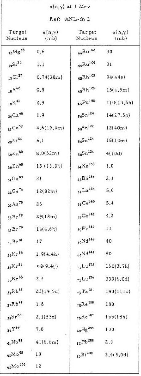
Media: n 2n x-section at 14.3 MeV.jpg
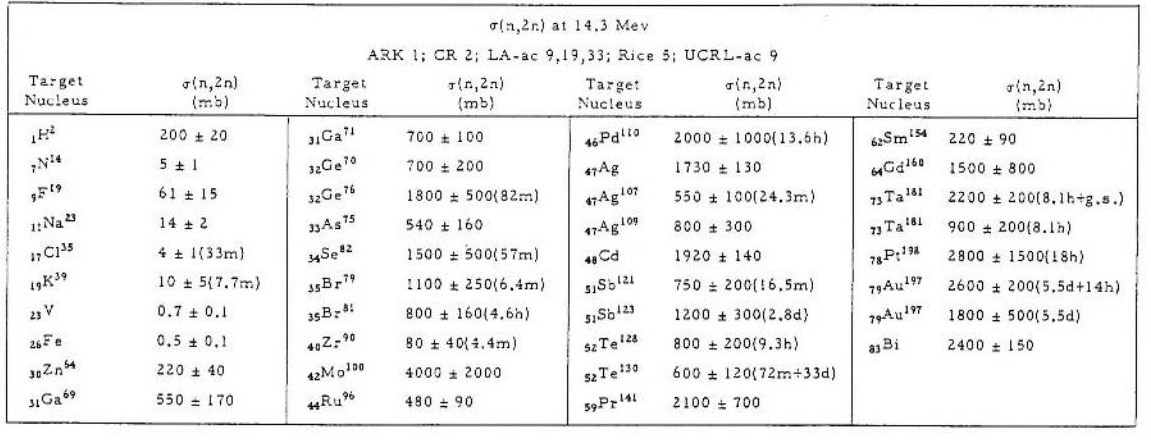
Donald James Hughes, Neutron cross sections, 2nd edition 1958, u.s.a atomic energy commission.Media:Neutron cross sections.pdf
File:NSAE 151 2005 319-334 Y.D. Lee.pdf
TGEM-2009 File:TGEM 2009.pdf
12 Volt power supply system.
http://www.lnf.infn.it/esperimenti/imagem/doc/NIMA_46128.pdf
http://electrontube.com.Media: rp097mono HV divier.pdf
http://www.cerac.com/pubs/proddata/thf4.htm#anchor550078
http://en.wikipedia.org/wiki/PC_board
GEANT4_Paticles_Models[2]
Resistors online store : http://www.justradios.com/rescart.html
RETGEMs
Media:Jinst8_02_p02012_THGEM_spark.pdf
- Thick GEM COBRA
Media: Nucl_Phys_B_Bidault_ novel UV photon detector.pdf
Media:Mauro micro pattern gaseuos detectors.pdf
Media:Development and First Tests of GEM-Like Detectors With Resistive Electrodes.pdf
http://www.supplydivision.co.uk/genitem.htm
Thick_GEM_versus_thin_GEM_in_two_phase_argon_avalanche_detectors (HV circuit)[3]
Stainless Steel deflection [4]
Th-Xsection references
File:Th-232 fxsection Behrens 0.7-1.4MeV.pdf
File:Th-232 fxsection Blons 1975 1.2-1.8MeV.pdf
File:Th-232 fxsection ermagambetov 0-3MeV.pdf
File:Th-232 fxsection Henkel 0-9MeV.pdf
File:Th-232 fxsection Ohsawa original.pdf
File:Th-232 fxsection pankratov 3-35MeV.pdf
File:Th-232 fxsection protopopov distancefromthesource.pdf
File:Th-232 fxsection rago 12.5-18MeV.pdf
U-238-Xsection and coating references
relative cross section and calibration samples characteristics for a well determined number of fissions per second
File:Eismont relative absolute nf induced intermediate energy.pdf
- U_238 cross section error analysis
INTERNATIONAL EVALUATION OF NEUTRON CROSS-SECTION STANDARDS, INTERNATIONAL ATOMIC ENERGY AGENCY,VIENNA, 2007 File:U238-xsection.pdf
U_238 (0.5-4MeV) and Th_232 (1-6MeV) fission cross section with statistical error.File:Th-232 U238 xsetion data ebars.txt
File:Pankratov fxsection Th232 U233 U235 Np237 U238 5-37MeV.pdf
Thorium Coating
ThF4 target for sputtering coatings
http://www.cerac.com/pubs/proddata/thf4.htm
Machining Uranium
Uranium will ignite in powder form
http://www.springerlink.com/content/rr072r52163x0833/
- coating Uranium
http://cat.inist.fr/?aModele=afficheN&cpsidt=16864172
Calorimeters/Detectors: DU sheet is in wide-scale use as an absorber material in high-energy physics research at large accelerator laboratories. The high atomic number and density of DU presents a large number of atoms per unit volume to interact with the particles emerging from collisions in these detectors. Also the slight background radiation from DU enables in situ calibration of the electronic read out devices within such detectors, thereby improving the accuracy of measurement.
http://www.2spi.com/catalog/chem/depleted-uranium-products.html
- IAEA Photonuclear Data Library [5]
- Data Acquisition
Warren_logbook[6]
Warren_Thesis [7]
Related To Gaseous Detectors
Breakdown and Detector Failure (10/21/10)
- Different kind of micro-pattern detectors
- References
1- A. Bressan, M. Hocha : NIM A 424 (1999) 321—342 File:High rate behavior and discharge limits in micro-pattern detectors .pdf
2- Fonte and Peskov IEEE 1999 :File:Fundamental limitations of high rate gaseous detectors.pdf
3- B. Schmidt: NIM A 419 (1998) 230—238 File:Microstrip gas chambers Recent developments radiation damage.pdf
Ideas
1.) Can we mix resistive paste (Encre MINICO) with TH-232. We construct a "bed of nails" to place a predrilled G-10 board with a copper border. The nails fill in the holes of the G-10 to keep the paste out. Ecre MINICO is a resistive paste used for transistors.
a.) Get some resistive paste.
http://www.leggesystems.com/p-253-elimstat-uxm-ccp.aspx
Resistive glue to compare
http://www.ellsworth.com/conformal.html?tab=Products
http://www.ellsworth.com/display/productdetail.html?productid=764&Tab=Products
http://www.ellsworth.com/display/productdetail.html?productid=2067&Tab=Products
http://www.cotronics.com/vo/cotr/ea_electricalresistant.htm
b.) mix with a metal similar to Th-232.
c.) construct bed of 0.4 mm nails. Look for 0.4 mm diameter pins.
7/31/2009
New vendor for carbon paste.
http://www.electrapolymers.com/productItem.asp?id=33
The data sheet does not show any information about the thickness of the paste.
The company has a distributor in the usa (877)-867-9668. A phone call is expected on Sat. 8/3/2009 about the availability of the product.
TGEM Mask Design
Coating U-238 or Th-232 is essential for neutron detection in the range 2-14 MeV, but THGEM contains holes that should be protected from any coating material. So, a mask is designed to cover these holes. The holes are in drilled to be on the corners of hexagonal of 1mm side length as in the figure:

The mask is made of stainless steel, 10 um laser tolerance with cut the plate to get the shape in the figure:

Please look at the following files for more details:
Make number bold black font. Add color so it is clear that they are holes in a material.
P_D
Vendor
Thick Film Screen Printers
http://www.sciquip.com/browses/browse_Cat.asp?Category=Screen+Printers