Difference between revisions of "Neutron TGEM Detector Abdel"
| Line 281: | Line 281: | ||
;Status Indicator LEDs | ;Status Indicator LEDs | ||
| − | Green indicates enough power is provided to the board(2.25V), the green light becomes dim when there is a voltage drop (<2.25V).Yellow or red | + | Green indicates enough power is provided to the board(2.25V), the green light becomes dim when there is a voltage drop (<2.25V).Yellow or red indicate an error or a problem in the board, and can y be set by the I2C Expander chip. |
=Summary Sorma 2012= | =Summary Sorma 2012= | ||
Revision as of 19:50, 7 November 2012
Garfield
Electric Field distribution
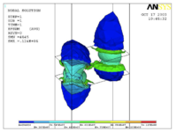
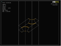
The figures represent the simulation of the electric field by using 1/4 hole in THGEM card that is made of FR4 and covered with resistive paste.
The figures represent in order : the THGEM hole model design, electric field simulation of the recent THGEM hole model that has a diameter 0.5mm and 0.9mm rim diameter(we are testing in the lab now), and the last figure represents the THGEM hole simulation after changing the hole's inside shape from the cylindrical shape to cone shape for the top and the bottom part of the hole (so it looks like the hour clock or sand clock shape). The new change in shape will change the E-field strength around and inside the hole to higher values, also it changes the electric field lines distribution outside the hole. The new simulated hole model consists of two cones that have the 0.5 diameter area in contact, each has a an inner diameter of 0.5mm and an outer diameter is 0.8mm, the rim still has 0.9mm diameter without any change.
Garfield simulation for GEM foils
- Single GEM
Garfield simulates a single GEM that has the standard structure
pitch = 0.14 ! Distance between holes, in mm
kapton = 0.050 ! Thickness of the kapton layer, in mm
metal = 0.005 ! Thickness of the meta layers, in mm
r_o = 0.050 ! Hole outer diameter, in mm
r_i = 0.070 ! Hole diameter in the centre, in mm
The simulation results:
Triple GEM:
The results for triple GEM:
ComponentAnsys123::Initialise:
Read properties of 3 materials from file MPLIST.lis.
ComponentAnsys123::Initialise:
Read 31297 elements from file ELIST.lis,
highest node number: 48073,
background elements skipped: 0
ComponentAnsys123::Initialise:
Read 48073 nodes from file NLIST.lis.
ComponentAnsys123::Initialise:
Read 48073 potentials from file field.lis.
MediumMagboltz::SetComposition:
Ar/CO2/CF4 (45/15/40)
MediumMagboltz::EnablePenningTransfer:
Penning transfer parameters for 44 excitation levels set to:
r = 0.55
lambda = 0 cm
Number of materials: 3
The permittivity of material 0 is 1e+10
The permittivity of material 1 is 3.5
The permittivity of material 2 is 1
Sensor::AddElectrode:
Added readout electrode "readout".
All signals are reset.
Sensor::SetTimeWindow:
Resetting all signals.
Avalanche 0 - electrons = 6479, ions = 7113 (started at 0.82 sec)
Avalanche 1 - electrons = 7548, ions = 8340 (started at 1489.31 sec)
Avalanche 2 - electrons = 6801, ions = 7531 (started at 3305.48 sec)
Avalanche 3 - electrons = 7956, ions = 8678 (started at 5048.83 sec)
Avalanche 4 - electrons = 8962, ions = 9860 (started at 6960.89 sec)
Methane percentage calculation if P10 bottle gas totally leaks in the LDS
P10 gas consists if 90/10 Ar/CH4.
A flammability hazard exists when the methane percentage is 5-15 percent (STP) (ref. http://encyclopedia.airliquide.com/Encyclopedia.asp?GasID=41) in the LDS.
The LDS volume in meters is
The volume of the cylinder is =
Assuming the bottle pressure is 2200 psi (149.7 atm), the Methane volume at atmospheric pressure is :
If the Methane is trapped in the LDS room. (assuming the doors are close and there is not any ventilation). The percentage of Methane trapped by the LDS space is .
No more than 20 bottles of P10 may be in the LDS at any given time.
The maximum voltage on a copper THGEM card
The new copper thick GEM cards (t = 0.43 mm , d= 0.3mm, a= 0.8mm) are tested to check the maximum voltage that can be applied between the top and bottom of the card with the least harmful sparking probability. The cards are placed inside the chamber with a vertical distance of 3.4 and 2 mm from the grounded readout plate, then placed again with the same vertical distance but without grounding the readout plate. The results are represented in the following table:
| Card Number | 3.4mm grounded // 3.4mm without ground | ||
| 90/10 ArCO2 | P10 | P5 | |
| 1 | 1500 | 1330 // 1375 | 1200 // 1230 |
| 2 | 1400 | 1140 // 1180 | 1200 // 1180 |
| 3 | 1500 | 1150 // 1183 | 1130 // 1000 |
| 4 | 1300 | 1250 // 1290 | 1120 // 1107 |
| 5 | 1400 | 1500 //1550 | 1350 // 1550 |
| Card Number | 2mm grounded // 2mm without ground | ||
| P10 | P5 | ||
| 1 | 1200 // 1275 | 1121 // 1125 | |
| 2 | 1025 // 1113 | 1100 // 1200 | |
| 3 | 1100 // 1130 | 975 // 1025 | |
| 4 | 1200 // 1130 | 1000 // 1050 | |
| 5 | 1550 // 1650 | 1400 // 1450 | |
What was the max V when the cards were in the detector.
950V, the separation distance was 2mm from the ground (for THGEM2), and 3-4 mm between the cathode and THGEM 1.
V1495_USR_firmware (Warren's thesis)
It is provided by the manufacturer (CAEN) to guide to the V1495 uses.
GEMReadout Firmware Modules
- VHDL Modules
| Module Name | Tasks or description |
| v1495usr.vhd | it contains all I/Os as can be seen on the Pinout |
| tristate_if_rtl.vhd | contains the logic necessary to control the direction of the FPGA data bits found in v1495usr.vhd and the logic to control the direction of the bidirectional I/Os associated with the VME data bus. |
| spare_if_rtl.vhd | contains the logic necessary to control the direction
of the spare bidirectional I/Os included with the Cyclone FPGA. |
| GEMReadout.vhd | This module handles all of the receiving and transmitting functionality to and from the VFAT ICs, the FIFO storage, the PLL timing (if used), control of the LEDs on the V1495 and the ROC interface capabilities via the VME bus. |
| GEMTrigger.vhd | The GEMTrigger module handles the conversion of a single-pulse trigger to a 3-bit (or 8-bit in the case of the Calibration Pulse signal) trigger word which is sent to the T1 line of the VFATs and is in sync with the MCLK. |
| v1495usr_pkg.vhd | contains the offset address for all of the user registers of the v1495. |
| PLLBlock.vhd | replicate the original MCLK signal coming in on G0 and outputting it to the PLLCLK signal. It creates a clock signal that is an exact inverse of this signal (PLLCLK_90), it allows t he user to change the frequency between 15Mhz and 1Ghz. |
| GEMRxEventDataFIFO.vhd/ GEMRxEventSizeFIFO.vhd | contain the specific layout of the DataFIFO and the SizeFIFO and both are extremely similar in layout. |
| GEMRxChannel.vhd | governs the behavior of the data received from the VFATs on their respective DataOut and DataValid channels. |
| GEMTxChannel.vhd | provide debugging methods for the basic functionality of the I/Os on the V1495 |
| GEMReadout_tb.vhd | provides a useful test bench with which to test the basic I/O functionality of the V1495 when one does not have access to VFAT chips for generating and capturing data packets. |
- Verilog Modules
| Module Name | Tasks or description |
| v1495usr_hal.vqm | contains many of the logical functions that serve as a building foundation for the v1495 module, automatically generated using the Synopsys Synplify design entry/synthesis tool which is used to create, synthesize, and optimize a project and then generate a Verilog Quartus Mapping file (.vqm). |
Readout Control libraries
| Function Name | Tasks or description |
| v1495Init | This function establishes a pointer value for the V1495 VME card within the MVME6100 memory map |
| v1495ReadEvent | queries the VFATs and then stores their data into the “V1495ReadoutStatus” struct before getting parsed up and sent to the DAQ. |
| v1495FillData | This function simply takes a pointer to a 32-bit integer and fills it with the data from the structs of type “V1495ReadoutStatus” with 32-bit “chunks. |
| v1495Sprint | This function is a watered-down printout of some of the most useful registers recorded by the V1495 after a query of the VFAT data. |
| v1495StatusPrint | outputs a Number of TotalBytes, a Number of TotalFrames, Number of Sent Bytes, VFAT serial data in hexadecimal, 32-bit segments. |
| v1495HextoBin | changes the hexadecimal values reported in the v1495StatusPrint function to their binary equivalent. |
| v1495test | This function prints off several key registers found in the V1495. |
| v1495reload | called from within v1495firmware and simply reboots the User FPGA by writing a ‘1’ to the USER FPGA Configuration Register. |
| v1495firmware | write the “standard” image or the “backup” image,generate files using Quartus II and should have the extension “.rbf”. |
| v1495release | sets the v1495 pointer to a NULL value |
| v1495DataReady | uses the FIFOLength register to determine which VFAT has the greatest number of entries. |
| v1495CalPulse | takes the parameter passed to it to instruct the V1495 to send that number of CalPulses to the VFATs. |
| v1495Reset | resets the V1495. |
| Other VxWorks Debugging Programs | m <32-bit address>,<Number of Bytes>40
The ‘m’ stands for “modify”, command helps one to write to a given register address. Hit Enter if you don’t want to change a value. Enter a ‘.’ and hit enter to exit the function.d <32-bit address>,<Number of Bytes> ‘d’stands for “dump” – displays the values for the requested the hexadecimal number of bytes. Enter a ‘.’ to exit the function. |
Breakout Board
Breakout board tasks
1- employs several noise cancellation techniques which were utilized in this experiment.
2- Built-in radiation protection of the VFAT, charge-discriminating ICs, namely the Single Event Upset (SEU) triplicated logic and the Scan Chain ability for detecting erroneous digital gates.
Breakout board features
- Status Indicator LEDs
Green indicates enough power is provided to the board(2.25V), the green light becomes dim when there is a voltage drop (<2.25V).Yellow or red indicate an error or a problem in the board, and can y be set by the I2C Expander chip.
Summary Sorma 2012
Due to the demand on robust, economical, large active area compatible and gamma discriminating detectors, we started our work to build then measure the efficiency of Thick Gaseous Electron Multiplier Preamplifiers (THGEM) as a Neutron Sensitive Detector in the range of 1-14 MeV. The THGEM is constructed using an FR4 substrate that has been coated with a resistive paste or a thin layer of copper. A staggered array of millimeter size holes are machined in the THGEM. The resistive paste is removed from the perimeter of the holes in order to reduce the spark discharge probability. By doping the resistive paste with a neutron sensitive material A determination of the neutron sensitive material type and optimal doping strategy to produces a high detection efficiency.
ACNS 2012
A neutron detector is being constructed that uses Thick Gaseous Electron Multiplier preamplifiers (THGEM) and a thin film of a fissionable material. The THGEM is constructed using an FR4 substrate that has been coated with a resistive paste to reduce disharge events uncorrelated with an incident neutron. A staggered array of millimeter size holes are machined in the THGEM. The detector includes a segmented charge collector which is used to determine the potisiton of the neutron as it enters the detector's acceptance. The detector's efficiency for neutrons having energies between 1 and 14 MeV will be quantified using an accelerator based neutron source.
The Gaol in participating in ACNS school
Being a neutron detector research student, I am always interested in all neutron science developments and applications. A recent goal of my work is developing a fast response neutron detector using THGEM (thick gaseous electron multiplier) preamplifier, and neutron imaging using segmented charge collector technology. Such a combination between two technologies requires a knowledge of the latest neutron detectors' uses and of other instrumentation used in experiments. Participating in your school is a step to gain experience in this field, and offers a golden opportunity to communicate with specialists and scientists who have remarkable achievements in this field.
ISU research symposium
http://www.isu.edu/bulletinboard/student/xcall-03_19_2012_so.html
Due to the demand on robust, economical, large active area and gamma discriminating detectors, we started our work to build then measure the efficiency of Thick Gaseous Electron Multiplier Preamplifier (THGEM) as a Neutron Sensitive Detector in the range of 1-14 MeV. The THGEM is constructed using an FR4 substrate that has been coated with a resistive paste or a thin layer of copper. A staggered array of millimeter size holes are machined in the THGEM. The resistive paste is removed from the perimeter of the holes in order to reduce the spark discharge probability. Basically , the incident particle causes an ionization within the active area, most of the free electrons will drift through the holes by the the electric field causing an electron multiplication. The project THGEM model has a hole diameter of 0.5mm and rim size of 0.2mm, which allows the voltage between the top and bottom side of the Preamplifier to go up to 2kV. We are expecting a gain of 105 electron when a gas chamber filled 90/10% Ar/CO2 gas mixture has four THGEM Preamplifiers, each has a voltage close to 2kV. By doping the resistive paste with a neutron sensitive material A determination of the neutron sensitive material type and optimal doping strategy to produce a high detection efficiency.
THGEM test 2/15/12
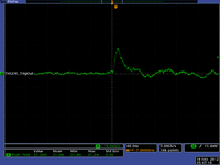
Four THGEM Card Model were tested and the pulses below were observed.
The distances in of : Cathode is 11.5mm, THGEM card distance is 4.6mm, readout distance : 6.9mm
Nothing is observed on the readout card!
3/28/12
- Conical copper THGEM cards are in the machine shop and may be done by next week
- 5 resistive paste cards are in the LDS
- Succeeded to run Garfield example GEM.C (error message: couldn't reach a Garfield text file)
To Do:
- Tomorrow install 4 THGEM cards into test chamber with advisor
- Document Garfield results from GEM.C
U-238 fission cross section in EPS format for Dr. Forest
File:ENDF GEAN4 U238 fxsection.eps
5/11/12 3-THGEM copper card detector testing results
- There was not any signal observed from the detector for cosmic rays or for the gamma source, the maximum voltage applied on each card (top and bottom) was 1.7 kV, and the trasmission voltage was 0.9 kV (between the cards), the distance between the cards was 2.3 mm, the same distance used to separate the cathode from the first THGEM card.
- Strong sparking was observed when the applied voltage on the cards was equal or more than 1.8 kV (as the THGEM cards and the cathode were placed with the same distances mentioned before), the sparking wass not in the holes area but on the other areas around the holes on the surface of the THGEM card. The spark was strong enough to damage a 1kV rated capacitor (for the fifth time by today morning), to damage a 50 ohm terminator (0.5 W), and to cause an offset on the scilloscope channel if it was connected. (it is not recommended to connect the oscilloscope over night with the detector even if the voltage is 1.7 kV!)
- The cathode distance varied from 6.9 to 2.3 mm, but the changing the distance did not forbid creating the sparks in the holes area (for the largest seperation distance), or around the holes (for the smallest one).
- The next step (if you agree) is to reproduce the results of the published paper for using the THGEM copper cards to build an alpha detector, simultaneously I repeat the testing steps using 3 resistive paste card detector in the old gas chamber, then compare the results with the THGEM copper cards' results .
Efficiency of an alpha double-THGEM detector
Two THGEM copper foils (the foil has cone shape holes with inner diameter of 0.5 mm,and outer of 0.66mm, and a pitch distance of 1.25mm.) and a cathode were installed in the gas chamber with a separation of distance of 1mm, U-233 button source was also fixed in holes shadow area on the cathode.
a signal observed of width of 50ns and 1.5Hz frequency (in average).
A counting experiment is in progress to count the trigout signal from the THGEM detector, then another counting experiment for the U-233 source will be set up using an alpha proportional counter that has an efficiency of 30% (Roy will help in providing the equipment for the second part).
References
THGEM design
THGEM#9
Media:Shalem_MSthesis_march2005.pdf
Media:Raz_Alon_MSthesis_Dec2007.pdf
Electric field Simulation
- Rim size dependence
File:THGEM Efield simulation.pdf
- 2010 THGEM design(s)
File:THGEM 2009 design gas efficiency.pdf
Simulations_of_Particle_Interactions_with_Matter
Voss and 3 russian references for Dy(n,x) cross sections
http://arxiv.org/abs/0903.3819 Dy photon gammas spectrum
http://www.ippe.obninsk.ru/podr/cjd/kobra13.php?SubentID=30974002
http://www.americanelements.com/thoxst.html
http://arxiv.org/pdf/physics/0404119
NIM_A535_2004_93[1]
File:NIM A590 2008 pg134 Eberhardt.pdf Prep Targets
Neutron cross sections for different elements Media:Neutron_cross_sections.pdf
http://www-nds.iaea.org/RIPL-2/
Media:n gamma cross sections at 25 keV.jpg
Media:n alpha cross section at 14.2 MeV.jpg
Media:ne cross section at 14 MeV.jpg
Media:high enegy fission x-section.jpg
Media:N_gamma_x-section_at_400_keV.jpg
Media:x-sections of reactions at 14 MeV.jpg
Media:n p x-section at 14.3MeV.jpg
Media: n gamma x-section at 14.5 MeV.jpg
Media: elastic x-section at 0.5 MeV.jpg
Media: n gamma x-section at 1 MeV.jpg
Media: n 2n x-section at 14.3 MeV.jpg
Donald James Hughes, Neutron cross sections, 2nd edition 1958, u.s.a atomic energy commission.Media:Neutron cross sections.pdf
File:NSAE 151 2005 319-334 Y.D. Lee.pdf
TGEM-2009 File:TGEM 2009.pdf
12 Volt power supply system.
http://www.lnf.infn.it/esperimenti/imagem/doc/NIMA_46128.pdf
http://electrontube.com.Media: rp097mono HV divier.pdf
http://www.cerac.com/pubs/proddata/thf4.htm#anchor550078
http://en.wikipedia.org/wiki/PC_board
GEANT4_Paticles_Models[2]
Resistors online store : http://www.justradios.com/rescart.html
RETGEMs
Media:Jinst8_02_p02012_THGEM_spark.pdf
- Thick GEM COBRA
Media: Nucl_Phys_B_Bidault_ novel UV photon detector.pdf
Media:Mauro micro pattern gaseuos detectors.pdf
Media:Development and First Tests of GEM-Like Detectors With Resistive Electrodes.pdf
http://www.supplydivision.co.uk/genitem.htm
Thick_GEM_versus_thin_GEM_in_two_phase_argon_avalanche_detectors (HV circuit)[3]
Stainless Steel deflection [4]
Data Sheets
radioactive surface cleaner NoCount MDSD File:Radioactive surface cleaner.pdf.
Th-Xsection references
File:Th-232 fxsection Behrens 0.7-1.4MeV.pdf
File:Th-232 fxsection Blons 1975 1.2-1.8MeV.pdf
File:Th-232 fxsection ermagambetov 0-3MeV.pdf
File:Th-232 fxsection Henkel 0-9MeV.pdf
File:Th-232 fxsection Ohsawa original.pdf
File:Th-232 fxsection pankratov 3-35MeV.pdf
File:Th-232 fxsection protopopov distancefromthesource.pdf
File:Th-232 fxsection rago 12.5-18MeV.pdf
U-238-Xsection and coating references
relative cross section and calibration samples characteristics for a well determined number of fissions per second
File:Eismont relative absolute nf induced intermediate energy.pdf
- U_238 cross section error analysis
INTERNATIONAL EVALUATION OF NEUTRON CROSS-SECTION STANDARDS, INTERNATIONAL ATOMIC ENERGY AGENCY,VIENNA, 2007 File:U238-xsection.pdf
U_238 (0.5-4MeV) and Th_232 (1-6MeV) fission cross section with statistical error.File:Th-232 U238 xsetion data ebars.txt
File:Pankratov fxsection Th232 U233 U235 Np237 U238 5-37MeV.pdf
Thorium Coating
ThF4 target for sputtering coatings
http://www.cerac.com/pubs/proddata/thf4.htm
Machining Uranium
Uranium will ignite in powder form
http://www.springerlink.com/content/rr072r52163x0833/
- coating Uranium
http://cat.inist.fr/?aModele=afficheN&cpsidt=16864172
Calorimeters/Detectors: DU sheet is in wide-scale use as an absorber material in high-energy physics research at large accelerator laboratories. The high atomic number and density of DU presents a large number of atoms per unit volume to interact with the particles emerging from collisions in these detectors. Also the slight background radiation from DU enables in situ calibration of the electronic read out devices within such detectors, thereby improving the accuracy of measurement.
http://www.2spi.com/catalog/chem/depleted-uranium-products.html
- IAEA Photonuclear Data Library [5]
- Data Acquisition
Warren_logbook[6]
Warren_Thesis [7]
Related To Gaseous Detectors
Breakdown and Detector Failure (10/21/10)
- Different kind of micro-pattern detectors
- References
1- A. Bressan, M. Hocha : NIM A 424 (1999) 321—342 File:High rate behavior and discharge limits in micro-pattern detectors .pdf
2- Fonte and Peskov IEEE 1999 :File:Fundamental limitations of high rate gaseous detectors.pdf
3- B. Schmidt: NIM A 419 (1998) 230—238 File:Microstrip gas chambers Recent developments radiation damage.pdf
Ideas
1.) Can we mix resistive paste (Encre MINICO) with TH-232. We construct a "bed of nails" to place a predrilled G-10 board with a copper border. The nails fill in the holes of the G-10 to keep the paste out. Ecre MINICO is a resistive paste used for transistors.
a.) Get some resistive paste.
http://www.leggesystems.com/p-253-elimstat-uxm-ccp.aspx
Resistive glue to compare
http://www.ellsworth.com/conformal.html?tab=Products
http://www.ellsworth.com/display/productdetail.html?productid=764&Tab=Products
http://www.ellsworth.com/display/productdetail.html?productid=2067&Tab=Products
http://www.cotronics.com/vo/cotr/ea_electricalresistant.htm
b.) mix with a metal similar to Th-232.
c.) construct bed of 0.4 mm nails. Look for 0.4 mm diameter pins.
7/31/2009
New vendor for carbon paste.
http://www.electrapolymers.com/productItem.asp?id=33
The data sheet does not show any information about the thickness of the paste.
The company has a distributor in the usa (877)-867-9668. A phone call is expected on Sat. 8/3/2009 about the availability of the product.
TGEM Mask Design
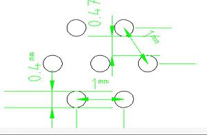
Coating U-238 or Th-232 is essential for neutron detection in the range 2-14 MeV, but THGEM contains holes that should be protected from any coating material. So, a mask is designed to cover these holes. The holes are in drilled to be on the corners of hexagonal of 1mm side length as in the figure:
The mask is made of stainless steel, 10 um laser tolerance with cut the plate to get the shape in the figure:
Please look at the following files for more details:
Make number bold black font. Add color so it is clear that they are holes in a material.
P_D
Performance of THGEM as a Neutron Detector
Vendor
Thick Film Screen Printers
http://www.sciquip.com/browses/browse_Cat.asp?Category=Screen+Printers
http://www.marubeni-sunnyvale.com/screen_printing.html
tektronix oscilloscope
134.50.3.73


