Neutron TGEM Detector Abdel
Haithem's logbook for developing neutron sensitive TGEM detector
AFCRD Reports-2011
- A vendor is being sought for a flex circuit version of the readout card adapter in order to allow the readout cards to attach to the detector more easily.
- A detector gas system upgrade is underway and should be completed before the next quarter
- A new TGEM card has been machined which was redesigned to reduce spark discharge between two adjacent TGEM preamplifier cards previously observed at 1.7 kV. The expectation is to reach a TGEM voltage of 2 kV with two preamplifier cards stacked on top of each other and separated by 2.5 mm.
Look for NE213 and NE230 liquid scintillator detectors for fast neutrons. Does the neutron leave the detector?
1/13/11
- Sparking Test
Sparking test for the HT-THGEM of holes size(76) and rim (63)
| Separation distance (mm) | type of gas surrounding | V1GB (kV) | V1GT(kV) | V2GB (kV) | V2GT (kV) | Notes |
| 6.5 | Ar/CO2 | 0 | ||||
| 5.0 | Ar/CO2 | 0 | ||||
| 2.6 | Ar/CO2 | 0 | -2 | +2 | -3 | sparking on the edge then holes starts to spark too |
| 2.6 | Air/CO2 | 0 | -2 | -2 | 0 | no sparking. |
where:
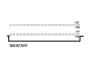
V1GB = bottom of the first THGEM card which is placed 2 mm above the charge collector
V1GT = top of the first THGEM card
V2GB = bottom of second THGEM card just above the first TGEM card.
V2GT = top of second THGEM card.
1/21/11
- The THGEM card is still sparking because of the hook up wires; which are tested up to 600V by the manufacturer.
The maximum voltage applied for one card only is 2000V on the top and 2000V on the bottom of the card. As soon as the voltage increases more than 2000V on the bottom of the card. a spark is seen in the hole that contains the hook up wire. There is an insulation problem may get serious specially if we still planning to apply 4kV and 6kV on the THGEM card.
The following website is offering hook up wires solid core and can hold up to 2000V, 24 gauge size.
http://caledonian-cables.com/product/Hoop-Up_Wire/UL_1430_Hoop-Up_Wire.htm
we may use the wires supported by the glu to have a good insulation.
- Next step is to repeat the experiment again but after adding the glu on the soldered parts.
Resistive paste thickness-mass calibration curve
- Aim
Studying the relationship between the mass and thickness of the resistive paste painted over 10X10 HTTGEM Foil.
- Experiment equipments and restrictions
Accurate scale (), SEM (scanning electron microscope).
SEM sample's height limit : 5 cm.
(Dr. David Peterson Assistant Professor in Anthropology,Research Scientist, Center for Archaeology, Materials and Applied Spectroscopy (CAMAS) , 157 Graveley Hall,Idaho State University)
- Procedure
Measuring the mass of Prepared samples of 0.5 thickness FR4 square plates with different surface areas as in the table below before and after painting the paste.
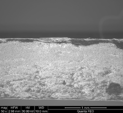
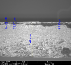
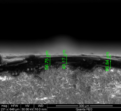
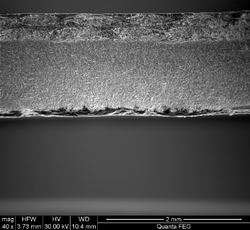
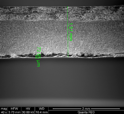
Studying the paste distribution and thickness under SEM.
- Experimental Data
| Plate Surface area (cm^2) (length ) | mass (g) before applying the paste | mass (g) after applying the paste | notes | |
| 1X1 | 0.2627 | 0.2634 | 0.7 | paste on both sides |
| 2X2 | 0.9776 | 0.9793 | 0.4 | paste on both sides |
| 3X3 | 2.5074 | 2.5074 | 0 | paste on one side |
| 4X4 | 4.4923 | 4.4940 | paste on one side | |
| 5X5 | 7.3261 | 7.3250 | paste on one side (paste is not uniform) |
- SEM Images
- 2x2 sample
| Image(a) | Image(b) | Image(c) | |
 |
 |
|
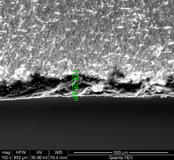
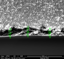
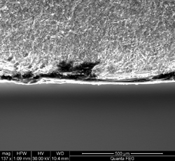
- 4x4 sample
| Image(1) | Image(2) | Image(3) | Image(4) | Image(5) |
 |
 |
 |
 |
|
- Conclusions and Next step(s)
-Using SEM is accurate enough to measure the paste thickness within few micros depending on the HFW (horixzontal field width) value (determined for each image).
- Highly recommended to use a high precision scale for measuring the mass variation accurately for each samples, not only for this experiment but also for the future samples that will contain a radioactive materials.
- Preferable size for the best image is 2x2 cm with clean edges and reference line.
- The resistive paste thickness changes from one sample to another and is not unform surface within the micrometer scale, for the 4x4 sample maxmimum value measured or the paste thickness was 120 um, and the minimum was 80 um. Successivly, the 2x2 sample paste thickness was measured with a maximum of 66.84 um and mimimum 49.17 um.
- The measurements were accurate whenever the paste is distiguished from the over flow of the paste on the edge, and as the charging on the sample is the least. (When the sample was inside the SEM-chamber, a beam of electrons hit the sample and created charged areas that soemtimes ddi not make the edge image sharp enough, this is clear by comparing image (4) and image (5)).
- New samples will be prepared, all have the 2x2 cm^2 area, with a small groove on the edge to have new images by SEM, each sample will have a cerain amount of the resistitive paste, the mass of the paste accuratlely be determined (hopefully) using a high presicion scale.
Experiment Tasks timetable
| Date | Task | Notes |
| 10/20/10 | Preparing the samples in different areas | Done on time |
| 10/21/10 | painting and curing the paste, measuring the mass before and after painting the paste | measuring the mass is accurate enough, even we borrow the scale and put it in table without anything around and without being moved just for the day of the taking the data or finding a more accurate one in a more stable measuring conditions. |
| 10/22/10 | studying the samples using SEM | CAMAS facility across Alvin Ricken Drive from the Idaho Accelerator Center, at 11:00 AM |
| 10/28/10 | studying the 2x2 samples using SEM | (postpone) CAMAS facility across Alvin Ricken Drive from the Idaho Accelerator Center, at 11:00 AM |
| 11/4/10 | studying the 2x2 samples using SEM | CAMAS facility across Alvin Ricken Drive from the Idaho Accelerator Center, at 11:00 AM ?? |
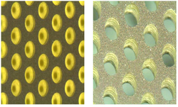
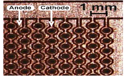
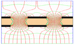
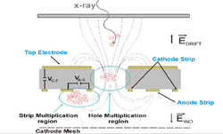
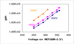
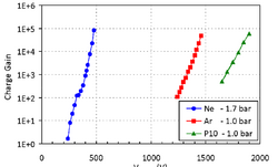
RETGEM vs. THCOBRA
| RETGEM | THCOBRA |
 |
|
 |
|
 |
|
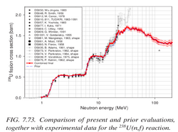
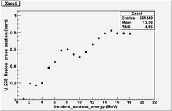
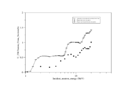
Comparison ENDF evaluation of U-238 neutron fission xsection and GEANT4
 |
 |
|
INTERNATIONAL EVALUATION OF NEUTRON CROSS-SECTION STANDARDS, INTERNATIONAL ATOMIC ENERGY AGENCY,VIENNA, 2007 File:U238-xsection.pdf
- absolute f_xsection in the table 7.1 p.91
| Ref. number | inxn | data description | author | citation | notes |
| 809 | 238U(n,f) | Absolute | G. Winkler et al. | 91Jülich (1991) 514 | the paper represents f_xsection ratio measurements of U_238 to Al_27, Na_24, Fe_56, Mn_56 * found in library QC770 N742 1992) |
| 810 | 238U(n,f) | Absolute | K. Merla et al. | 91Jülich (1991) 510 | * The paper represents f_xsection ratio measurements of U_238, U_235 , Np_237, and Pu_239 for 4.45 MeV, 8.46 MeV, 18.8 MeV * very accurate description for the experiment details and through the figures and the tables * found in library QC770 N742 1992) |
| 877 | 238U(n,f) | Absolute | I.M. Kuks et al. | At. Energy 30 (1971) 55 | *measured f_xsection U_238 fission for 2.5 MeV Neutrons |
| 860 | 238U(n,f) | Absolute | N.N. Flerov et al. | At. Energy 5 (1958) 657 | *title : antinutrino , Mean number of neutrons emitted in fission of U235 and U238 by 14-Mev neutrons, Mean number of neutrons emitted in fission of U235 and U238 by 14-Mev neutrons |
Done In April (edited by 04/30/10)
1.)Testing the new laminate with random holes after applying the resistive paste on both sides. Also, the trial of applying the paste was done, 0.1 inch brush is used for that to avoid covering the holes with the paste. the following procedure were taken:
a- Voltage is applied on the the foil to check the first sparking place.
b- Applying the paste carefully on the area between the holes with very small quantities.
- Result
a) Applying the paste shifts the sparking area to next neighboring one, so looks this will lead us to cover all the areas between the holes to kill the sparks.
b)A need to keep the foil under voltage to keep tracking of the sparks which lead unfortunately led to loss the voltage between the two copper layers.
Even a drop of paste got stuck in one of the holes(which has low possibility since I cleaned all the paste applied very well), or the two layers are no longer isolated from each other!
2.)Final touches on the HV-circuit are done, diagrams are done by eagle with Gerber files, the chamber is ready for redesigning.
3.)Running Th-232 fission simulation without ionization on inca and daq1. Energies 1-9MeV (inca) and 19-22 MeV(daq1) will be done by today(04/30/10).
4.)Tracking the process to get Th-232, contacting other vendors for radioactive isotopes, trying to get low cost ones.
Th-232 and U-238 Activity in mCi
General information:
| Physical properties | U-238 | Th-232 |
| Half life in years | 4.468 X 10^9 | 1.405 X 10^10 |
| Decay rate per second | 4.91 X 10^-18 | 1.56 X 10^ -18 |
| Molar Mass g/mol | 238.02891 | 232.0381 |
| Activity of 2 kg in mCi | 0.68 | 0.22 |
Avogadro's number is 6.0221 X 10^23 /mol
1 Ci = 3.7 X 10^10 disintegration/ second
References
- 2010 THGEM design(s)
File:THGEM 2009 design gas efficiency.pdf
Simulations_of_Particle_Interactions_with_Matter
Voss and 3 russian references for Dy(n,x) cross sections
Media:Shalem_MSthesis_march2005.pdf
http://arxiv.org/abs/0903.3819 Dy photon gammas spectrum
http://www.ippe.obninsk.ru/podr/cjd/kobra13.php?SubentID=30974002
http://www.americanelements.com/thoxst.html
http://arxiv.org/pdf/physics/0404119
NIM_A535_2004_93[1]
File:NIM A590 2008 pg134 Eberhardt.pdf Prep Targets
Neutron cross sections for different elements Media:Neutron_cross_sections.pdf
http://www-nds.iaea.org/RIPL-2/
Media:n gamma cross sections at 25 keV.jpg
Media:n alpha cross section at 14.2 MeV.jpg
Media:ne cross section at 14 MeV.jpg
Media:high enegy fission x-section.jpg
Media:N_gamma_x-section_at_400_keV.jpg
Media:x-sections of reactions at 14 MeV.jpg
Media:n p x-section at 14.3MeV.jpg
Media: n gamma x-section at 14.5 MeV.jpg
Media: elastic x-section at 0.5 MeV.jpg
Media: n gamma x-section at 1 MeV.jpg
Media: n 2n x-section at 14.3 MeV.jpg
Donald James Hughes, Neutron cross sections, 2nd edition 1958, u.s.a atomic energy commission.Media:Neutron cross sections.pdf
File:NSAE 151 2005 319-334 Y.D. Lee.pdf
TGEM-2009 File:TGEM 2009.pdf
12 Volt power supply system.
http://www.lnf.infn.it/esperimenti/imagem/doc/NIMA_46128.pdf
http://electrontube.com.Media: rp097mono HV divier.pdf
http://www.cerac.com/pubs/proddata/thf4.htm#anchor550078
http://en.wikipedia.org/wiki/PC_board
GEANT4_Paticles_Models[2]
Resistors online store : http://www.justradios.com/rescart.html
RETGEMs
Media:Jinst8_02_p02012_THGEM_spark.pdf
- Thick GEM COBRA
Media: Nucl_Phys_B_Bidault_ novel UV photon detector.pdf
Media:Mauro micro pattern gaseuos detectors.pdf
Media:Development and First Tests of GEM-Like Detectors With Resistive Electrodes.pdf
http://www.supplydivision.co.uk/genitem.htm
Thick_GEM_versus_thin_GEM_in_two_phase_argon_avalanche_detectors (HV circuit)[3]
Stainless Steel deflection [4]
Th-Xsection references
File:Th-232 fxsection Behrens 0.7-1.4MeV.pdf
File:Th-232 fxsection Blons 1975 1.2-1.8MeV.pdf
File:Th-232 fxsection ermagambetov 0-3MeV.pdf
File:Th-232 fxsection Henkel 0-9MeV.pdf
File:Th-232 fxsection Ohsawa original.pdf
File:Th-232 fxsection pankratov 3-35MeV.pdf
File:Th-232 fxsection protopopov distancefromthesource.pdf
File:Th-232 fxsection rago 12.5-18MeV.pdf
U-238-Xsection and coating references
relative cross section and calibration samples characteristics for a well determined number of fissions per second
File:Eismont relative absolute nf induced intermediate energy.pdf
- U_238 cross section error analysis
INTERNATIONAL EVALUATION OF NEUTRON CROSS-SECTION STANDARDS, INTERNATIONAL ATOMIC ENERGY AGENCY,VIENNA, 2007 File:U238-xsection.pdf
U_238 (0.5-4MeV) and Th_232 (1-6MeV) fission cross section with statistical error.File:Th-232 U238 xsetion data ebars.txt
File:Pankratov fxsection Th232 U233 U235 Np237 U238 5-37MeV.pdf
Thorium Coating
ThF4 target for sputtering coatings
http://www.cerac.com/pubs/proddata/thf4.htm
Machining Uranium
Uranium will ignite in powder form
http://www.springerlink.com/content/rr072r52163x0833/
- coating Uranium
http://cat.inist.fr/?aModele=afficheN&cpsidt=16864172
Calorimeters/Detectors: DU sheet is in wide-scale use as an absorber material in high-energy physics research at large accelerator laboratories. The high atomic number and density of DU presents a large number of atoms per unit volume to interact with the particles emerging from collisions in these detectors. Also the slight background radiation from DU enables in situ calibration of the electronic read out devices within such detectors, thereby improving the accuracy of measurement.
http://www.2spi.com/catalog/chem/depleted-uranium-products.html
- IAEA Photonuclear Data Library [5]
- Data Acquisition
Warren_logbook[6]
Warren_Thesis [7]
Related To Gaseous Detectors
Breakdown and Detector Failure (10/21/10)
- Different kind of micro-pattern detectors
- References
1- A. Bressan, M. Hocha : NIM A 424 (1999) 321—342 File:High rate behavior and discharge limits in micro-pattern detectors .pdf
2- Fonte and Peskov IEEE 1999 :File:Fundamental limitations of high rate gaseous detectors.pdf
3- B. Schmidt: NIM A 419 (1998) 230—238 File:Microstrip gas chambers Recent developments radiation damage.pdf
Ideas
1.) Can we mix resistive paste (Encre MINICO) with TH-232. We construct a "bed of nails" to place a predrilled G-10 board with a copper border. The nails fill in the holes of the G-10 to keep the paste out. Ecre MINICO is a resistive paste used for transistors.
a.) Get some resistive paste.
http://www.leggesystems.com/p-253-elimstat-uxm-ccp.aspx
Resistive glue to compare
http://www.ellsworth.com/conformal.html?tab=Products
http://www.ellsworth.com/display/productdetail.html?productid=764&Tab=Products
http://www.ellsworth.com/display/productdetail.html?productid=2067&Tab=Products
http://www.cotronics.com/vo/cotr/ea_electricalresistant.htm
b.) mix with a metal similar to Th-232.
c.) construct bed of 0.4 mm nails. Look for 0.4 mm diameter pins.
7/31/2009
New vendor for carbon paste.
http://www.electrapolymers.com/productItem.asp?id=33
The data sheet does not show any information about the thickness of the paste.
The company has a distributor in the usa (877)-867-9668. A phone call is expected on Sat. 8/3/2009 about the availability of the product.
TGEM Mask Design
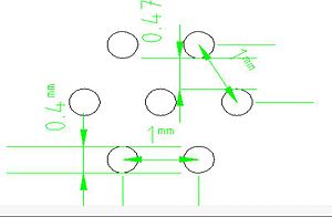
Coating U-238 or Th-232 is essential for neutron detection in the range 2-14 MeV, but THGEM contains holes that should be protected from any coating material. So, a mask is designed to cover these holes. The holes are in drilled to be on the corners of hexagonal of 1mm side length as in the figure:
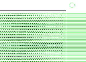
The mask is made of stainless steel, 10 um laser tolerance with cut the plate to get the shape in the figure:
Please look at the following files for more details:
Make number bold black font. Add color so it is clear that they are holes in a material.
P_D
Vendor
Thick Film Screen Printers
http://www.sciquip.com/browses/browse_Cat.asp?Category=Screen+Printers
