Neutron TGEM Detector Abdel
Haithem's logbook for developing neutron sensitive TGEM detector
1/23/09
image

1.) Search the web for patent which coats GEM detector with neutron sensitive materials. I think it is for Thermal neutrons.
Materials of high neutron capture cross section are studied widely, an example is the following patent
[[1]]
Most of the high neutron capture cross section materials were measured for different neutron energies. A comprehensive work is published in 2000. The project was supported by Korea Atomic Energy Research Institute and Brookhaven National Laboratory [[2]]
U-235 is the one of the best choices since it has a high neutron fission cross section and a long half life compared to other the other isotopes that may come under choice.
A second choice is Th-238 and U-238 which have fission cross section less than that of U-235 but still good for our experiment.[[3]]
A boron coated GEM foil is being made by the company below http://n-cdt.com/
Another method uses BF3.
We are interested in a fissionable material coated onto the copper foils that is thin enough to allow the fission fragments to escape the foil and ionize the gas in the detector.
2.) Search for companies which use either sputtering or coating technology to apply the above material to caopper PCboards with hole int them such that the material does not fill up the hole. Hole diameter = ?
The material sputter onto the copper would have thickness on the order of Angstroms.
The TGEM PCboard would have a surface area of 10 cm x 10 cm.
3.) Current neutron efficiency plots for several detector

Media:NeutronDetectionEfficiency-vs-Energy_Ne-213_BaF.pdf


1/30/09
1.) Investigate if Thorium Oxide will be a good candidate for the fission chamber. You would use electrolysis to coat a TGEM board.
Ways to make thorium fission chamber
2.) Find reference for THGEM9, this was used to determine optimal THGEM design 2 years ago
GEM-copper plate has dimensions of 3X3cm or 10X10cm with thinkness 5 micrometer copper layers.It has holes with diameter 60-80 micrometer.(From Operation of a triple GEM detector with CsI photocathode in pure BF4)
2/6/09
Thin deposition ThO2 molecular plating
2/13/09
Check if the people below can deliver Th coated Al or Cu sheets , coating thickness smaller than 5 micron, the thinner the better. http://www-wnt.gsi.de/tasca/
2/20/09
2.5 x 2.5 cm thorium coated TGEM cards coated by ISU chemistry.
chemistry Department cant not do the sputtering for safety purposes, they like to avoid radiation contamination.
Need a mask for the predrilled TGEM cards to prevent Thorium from entering holes
Radioactive waste procedure if we are allowed to sputter in chemistry.
Write report describing the process we want to do.
Radioactiving of Thorium may be a stumbling blog because of waste generated.
If we go for non-radioactive materials look up fission X-sect for Bismuth and Dysprosium
Fission cross section for Bi starts to be effective when the neutron energy is more than the range of interest.

Dy-isotopes are very good for absorbing neutrons in the range between 0.01- 10 MeV.

Media:Zaidi_RadChem_vol93_2005.pdf
2/27/09
1.) Dysprosium (Dy) makes a lot of gammas and maybe 100 less alphas
2.) Don't give up trying to make thorium coated materials
try to send e-mail to one of these authors
N. Takahashi, Zeitschrift für Physik A Hadrons and Nuclei Volume 353, Number 1 / March, 1995
3.) Fission cross-section n,f for Tb
3/13/09
1.) look for a company that does resistive evaporative coatings
This company sells the machine http://www.lesker.com/newweb/Deposition_Sources/ThermalEvaporationSources_Resistive.cfm
2.)(n,f) X-sect for Dysprosium (Dy) ?
3.) Thorium and thorium oxide thin films (19 to 61 nm thick) were RF-sputtered onto mirrors. RF sputtering onto copper plates?
The neutron fission cross sections of 92235U and 92238U between 0.3 and 12.5 MeV W W Osterhage et al 1978 J. Phys. G: Nucl. Phys. 4 587-595
http://www.inf.uu.se/Reports/publications.html
Neutron-induced fission cross sections of natPb and 197Au in the 45-180 MeV region, V.P. Eismont, A.V. Prokofiev, A.N. Smirnov, S.M. Soloviev, H. Condé, K. Elmgren, N. Olsson and P.-U. Renberg Conference Proc. ADTTA99, 1999, (in press).
Up-to-date status and problems of the experimental nucleon-induced fission cross section data base at intermediate energies, V.P. Eismont, A.V. Prokofiev, A.N. Smirnov, I.V. Ryzhov, G.A. Tutin, H. Cond, K. Elmgren, N. Olsson and P.-U. Renberg, Proc. ADTTA99, 1999, (in press).
Neutron-induced fission cross section ratios of 209Bi and 238U at 75 and 96 MeV, V.P. Eismont, A.V. Kireev, I.V. Ryzhov, S.M. Soloviev, G.A. Tutin, H. Condé, K. Elmgren, N. Olsson and P.-U. Renberg, Proc. ADTTA99, 1999, (in press).
Neutron-induced fission fragment angular distribution of 238U at 96 MeV, V.P. Eismont, A.V. Kireev, I.V. Ryzhov, S.M. Soloviev, G.A. Tutin, H. Condé, K. Elmgren, N. Olsson and P.-U. Renberg Proc. ADTTA99, 1999, (in press).
Measurements of neutron-induced fission cross sections of heavy nuclei in the intermediate energy region, V.P. Eismont, A.V. Prokofyev, A.N. Smirnov, K. Elmgren, J. Blomgren, H. Condé, J. Nilsson, N. Olsson and E. Ramström, Accelerator-Driven Transmutation Technologies and Applications, Kalmar, ed. H. Condé (Uppsala: Uppsala University, 1997) p 606-612.
4/2/09
Summury of events through the last two weeks:
1- Looking for a neutron fission cross section for Dyspromium.

2- Looking for other possile elements that can be sued beside our choices for Thorium and Dysprosium.
    these elemets should   have a high neutron cross for fission (n,f),(n,gamma),(n,p) or (n,alpha).
3- Using Neutrons cross sections (by D. Hughes and R. Schwartz, 2nd edition, 1957) as comphensive reference for our choice.
Comparison between Thorium and Dysprosium
.
Thorium: chacterized by relatively high neutron fission cross for both of its isotopes (Th-232 nad Th-230) compared to the stable elements but it is one of low fission cross sections compared to radioctive actinides. A lot of efforts are spent even in coating or finding the appropriate place or group to do that, since most of people are totally disencouraged to coat radioctive elements.


Dysprosium: radioactively stable,it has 5 isotopes Dy-160, 161, 162, 163 and 164. It is one of the best elements for detecting the neutrons because of high neutron capture cross section in the energy range of interest.


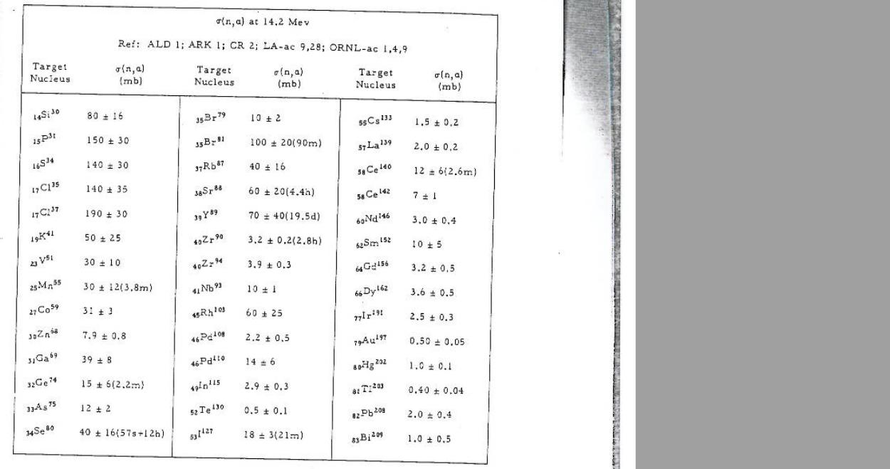
Also dysprosium pulls out alpha paticles (σ(n,α)= 3.6 mb at 14.2 MeV).
Other Possible Elements
. Generally,the highest values for neutron cross sections (σ(n,f), σ(n,p), σ(n,γ) and σ(n,α)) are for radioactive isotopes, which are not desirable for coating. Fortunately, there are non- radioactive elements have a relatively high neutron cross sections, for example:
σ(n,γ) at 0.025 MeV (in mb): Gd-158(710(70)), Sm-152 (670(100)), Br-81 (550(55)), Sm-154 (530(70)), Ce-142 (425(45)),
Hf-180(440(70)), Ru-96(320(60)), Ru-102 (390(40)), W-186 (300(40)), Zr-96 (240(40)), Hg-202(57(13))
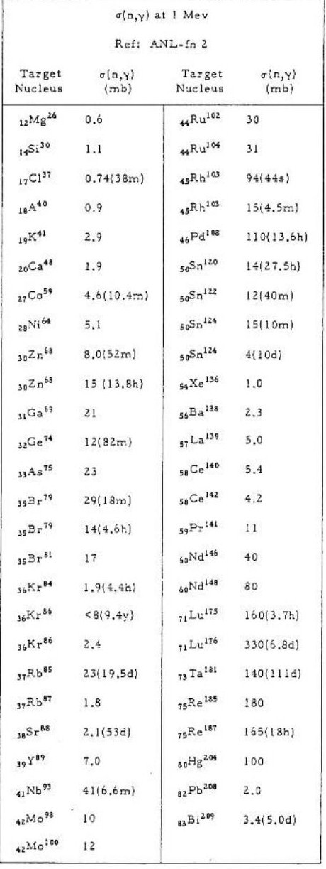
σ(n,γ) at 1 MeV (in mb): Re-185(180), (390(40)), Ru-102 (30), Ru-104 (31), Hg-204(100), Br-81 (17)
σ(n,γ) at 14.5 MeV (in mb): Gd-160 (19(5)), Zr-96 (<4),
| Element | X-sect (mb) |
| Re-185 | 180 |
| Ru-102 | 390 |
4/3/09
1.) Derive equations for voltages at each GEM stage and the net current for our voltage network and check them with measured values for the 4kV version of the voltage network.
2.) Reference [J.C. hadler, Radiation Measurements Vol 43 (2008) pf S334-S336] says
- R = 14 \mu m = mean range of fission fragment6s in U_3 O_8
- R= 12 um for UO_3
- 0.1 um thickness U( Th) will reduce mean length of fission tracks by 2%
3.) Plot N -vs- d using Equation 2 of Reference [J.C. hadler, Radiation Measurements Vol 43 (2008) pf S334 The number of particles per unit area is given by the equation:
d : the thickness in (um)
The range of the fragments in the emulsion is 12.07 um
.jpg)
4/17/09
A call conference with Dr.Wolfe, As result, the following is considered as next step for the project:
1- Check the melting temperature that a PC boeard can hold ( the size of the chamber can hold the 10 X 10 PC board ).

   The experiment is done, the temperature in average was aroubd 305oC, the PC board can hold that temperature easily,
the PC board was just burned since the medium around is O2, but there is one thing I want ot be sure of, if the PC board has a very light layer of certain material covers its surface and can't hold up that temeperature?
  An experiment is done today (4/30/09) to check the PC board behavior at 350oC.
  A peace of copper sticked by normal used glue.

PC boeard can't hold up the temperature 350oC.

2- Checking from a vender for chunk bulk ThF4 with size min. 30 cc.
3- Checking the thermal properties of ThF4 specially the melting point and if Thorium is adhere to copper in that temperature.
4- A mask should be prepared from stainless steal (Al is not preferable),inaddtion to thinking of drilling process and who
    is going to do it.
Laser machining can cut 1" stainless steel sheets
5- Dr. Forest is going to send the email after collecting all the information needed to Dr. Wolfe.
Coaing process is going to be by electron beam, thorium should be heated to 1750 C. (the melting point for pure Th).
Until this point the uniformity of the surface is not an important factor, but I think it would be important whenever we start thinking of the track and the direction for Th fission fragments.
4/23/09
1- Check the melting temperature that a PC board can hold ( the size of the chamber can hold the 10 X 10 PC board ).
Basically FR-4, FR-1, CEM-1 or CEM-3 PCB are made of polytetrafluoroethylene which has (327 °C (620.6 °F))as a melting point.
The experiment is done, the temperature in average was around 305 °C, the PC board can hold that temperature easily,the PC board was just burned since the medium contains O2, but there is one thing I want to be sure of, if the PC board has a very light layer of certain material covers its surface?
2- Checking from a vender for chunk bulk ThF4 with size min. 30 cc.
http://www.element-collection.com/RGB_Elements_OCT04_rev05.pdf
Element-collection sells thorium with 190$/gram !
3- Will Thorium adhere to copper
Thorium flouride is used for optical purposes, according the technical applications they have a number of recommendations related to sputtering by E-beam, and other materials that helps in thorium flouride adhesion.[4]
Looks there is a little change, Dr. Forest is going to check a vendor for U-238, which has a better fission cross section (3 times higher compared to Th-232),in addition to , the high price for Th-232 and risk of having flakes after sputtering, Throium by itself does not adhere with the surfaces unless other materials are used through the sputtering process (as methioned in the case of coating glass with thorium fluoride).
5/1/09
1.) Results from PCboard heating test: Board melts at 350 but not 310 degrees Celcius (Documents suggest 327 as the melting point.)
| Before heating to 350 | After Heating to 350 |
 |

|
| Before heating to 298 | After Heating to 298 |
 |

|
The experiment is done on the PC-board, it was heated for an hour under 298°C. The result is shown by the second photo, looks that PC-board should be replaced by another material that can hold this temeperature for longer time.
2.) Oak Ridge will give us 1 kg of metal Th-232. We pay for shipping and we need to do rad licenses. Dr. Forest e-mail Dr. Brey and the paper work is beginning.
Contact info
Lloyd J. Jollay Manager Nuclear Technology and Nonproliferation Y-12 National Security Complex P.O. Box 2009 Oak Ridge, TN 37831-8112 Office: 865-241-1872 Fax: 865-574-5169 Pager: 865-873-9146 Mobile: 865-206-9663
3.) Laser cutting can do up to 1" thick stainless steel sheets, we can make a mask! Need to learn CAD to create a drawing of the mask which will be uploaded to the laser cutting machine. make tolerances around 500 micron (1/2 mm).
Insert picture of our GEM PC board with a table of distances.
4.) Meting Point for U-238 =?
Melting Point: 1408 K (1135°C or 2075°F). Boiling Point: 4404 K (4131°C or 7468°F)
5/8/09
1.) It appears the FR-7 melts at 220 celsius so we may not be able to coat copper clad FR4 with U-28 or Th-232. This means we will most likely coat a copper sheet which is attached to a frame for tension and then laminate FR4 after we have coated the copper sheet with U-28 or The-232.
Determine melting point of our current PC boards.
Melting point for the PC board is 260 degrees Celsius,within this degree a change took place in the shape of the board which will make the possibility to use it for sputtering process is very little, the color of the PC-board starts to change at 200 degrees Celsius.
| 200 | 210 | 260 |
 |
 |
 , , 
|
2.) The distance between holes in the TGEM appear to be 1mm. A laser can cut through 1" of stainless steel. What accuracy can the laser have when cutting through the thinnest available SS we want to use for a mask.
Find laser resolution (200 microns?)
The following company [5] can reach to a tolerance of 10 micrometer if the thickness of the plate is bigger than 300 micrometer, in our case the thickness of copper foil is 45 micrometer, and the hole is diameter is 1 mm, a tolerance of 200 micrometer is going to be good for the drilling the holes and doing the mask. an email from the company will confirm the expectations.
Determine thinnest SS mask
still waiting for the email.
3.) HV distribution chain calculation. Low voltage version?
Order resistors based on power calculation, work with Tumuna on the order.
4.) Install GEANT4 in your Inca account, Start GEANT4 Fission model (CHIPS or GEISHA).
5/15/09
1.) Insert picture of PCboard at 220 and 260 and denote time spent at that temperature.
2.) The distance between holes in the TGEM appear to be 1mm and are staggered between rows. A laser can cut through 1" of stainless steel. We would like a laser with position accuracy to at least 100 microns (4 mils :1000 mils = 1 in) which can drill a hole whose diameter is accurate to 4 mils. What accuracy can the laser have when cutting through the thinnest available SS we want to use for a mask.
Find laser resolution (10 microns?)
Determine thinnest SS mask
3.) HV distribution chain calculation. Low voltage version?
Look at the following diagram :Media:GEM_HV_circuit.ps

Order resistors based on power calculation, work with Tumuna on the order
4.)GEANT4 is installed in Inca account, ExampleN02 was compiled and runs.
Add GEANT4 Fission model (CHIPS or GEISHA) to ExampleN02 program. Goal is to find a model which reproduces the X-section data for Th-232 above.
5/22/09
1.) heat PC board for 3 hours at 210C
2.) Determine laser resolution for a 45 micron thick copper sheet
3.) HV distribution chain calculation. Do a sample calculation for =?
4.) Going to order 25 resisters of each Ohm setting. Prepare a HV board for stuffing and assemble after resistors arrive.
5.)Add GEANT4 Fission model (CHIPS or GEISHA) to ExampleN02 program. Goal is to find a model which reproduces the X-section data for Th-232 above.
6/9/09
1.) Write a brief description ( 2 paragraphs) of the experimental objectives and methods with justification for the specific radionuclides and quantities.
We propose constructing a fission chamber which contains copper PCboards coated with U-238 and Th-232. Our goal is to construct a fast neutron detector. A safe in the LDS will serve as a repository for the U-238 and Th-232 bulk material. A small fraction of the material (100 g) will be sent to a collaborator at another University who will use Electron Beam-Physical Vapor Deposition to coat a 10 cm x 10 cm PCboard with U-28 or Th-232. The radioactive material will be a 5 micron or less coating attached to the PCboard. The PCboard will reside inside a gaseous detector. The quantities of each bulk material are given in the table below. Oak Ridge national Lab will supply 1kg of Th-232 at no cost. Unfortunately, 1kg is the smallest size available.
| U-238 | Th-232 |
| 200 g | 1000 g |
U-238 has a atomic number 92, and mass number of 238.050785, it is mainly an alpha emitter. Th-232 has a atomic number 90, and mass number of 232.038051 , it is also an alpha emitter.
2) Describe the facility used to store the materials, diagram of room layout. location of safe.
A floorplan of the Laboratory for Detector Science is shown below.
Media:LDS dimension Model(1).pdf
The LDS has 2 safes available for storing radioactive materials. A solid steel safe manufactured by Bunker Hill with the outer dimensions of (25 cm)H X (35 cm) W X (25 cm) D and inner dimensions of 9-1/2” H X 13-1/2” W X 9-5/8” is controlled by a digital lock. The safe itself weighs 15 kg and is mounted to a wall in the LDS. A second iron safe, manufacturer unkown, uses a combination lock and has the outer dimensions of 62 H X57 W X 45 (cm)D.
3.) Describe radiation survey instruments available for monitoring.
We ask that the TSO provide us with all necessary monitoring devices.
4.) Description and estimate of radioactive waste being generated.
We do not expect to generate radioactive was.
6/12/09
1.) heat PC board for 3 hours at 210C
| 210 |
|
|
2.) Determine laser resolution for a 45 micron thick copper sheet
50 micron
3.) HV distribution chain calculation. Do a sample calculation for =?
resisters have arrived currently soldering ready to measure HVs (remember, Digital voltmeter has 1 kV max)
4.)Add GEANT4 Fission model (CHIPS or GEISHA) to ExampleN02 program. Goal is to find a model which reproduces the X-section data for Th-232 above.
6/19/09
1.) Th-232 mask due July 1,2009
2.) HV distribution chain calculation. Do a sample calculation for =?

3.)Add GEANT4 Fission model (CHIPS or GEISHA) to ExampleN02 program. Goal is to find a model which reproduces the X-section data for Th-232 above.
6/30/09
1.) Th-232 mask due July 1,2009
change design to be a series of lines covering the holes. Calculate the % area of the foil to be covered with Th-232.
2.) Insert HV distribution chain measurements in table form and compare to calculation.
Input Voltage = 1000 V
| Current | measured | calculated |
| (uA) | 262.3 | 220.7 |
From the figure above:
3.)Add GEANT4 Fission model (CHIPS or GEISHA) to ExampleN02 program. Goal is to find a model which reproduces the X-section data for Th-232 above.
Contact F.W. Jones, TRIUMF, 03-DEC-96 and ask for suggestion on simulating Th-232 (n,f) in GEANT4. Which model to get X-sections right?
F.W. Jones sent by July, 7:
G4LFission is based on the GHEISHA model of fission, by H. Fesefeldt, from GEANT 3.21.
It is a parameterized model using empirical formulas, e.g. the one for average number of neutrons. The photofission part of the model is not implemented.
My role in this was mainly as a code translator, so unfortunately I can't give you an expert opinion on it. I would suggest that for your study, use one of the prepared physics lists which will include the optimal treatments of fission for various applications.
See e.g. http://geant4.cern.ch/support/proc_mod_catalog/physics_lists/referencePL.shtml
If you are in doubt about choosing a physics list, I would strongly recommend that you post a query on the Geant4 forums, describing your application and what you wish to study (indicate if you wish to study nuclear fragments or other yields).
The forum for hadronic physics is here:
http://hypernews.slac.stanford.edu/HyperNews/geant4/get/hadronprocess.html
This forum is monitored by experts who will be able to provide a more definitive answer.
Best regards, Fred Jones
7/10/09
1.) Th-232 mask due July 1,2009
Making the lines as wide as the holes consumes 50% of the surface area.
A 0.45 mm diameter circle covering the holes and connected by 0.3 mm thick lines will increase the area available for fissionable material to 64%.
Decision is to create a series of lines 0.4 mm thick to cover the holes and connect them with support material.
We need a design of lines 0.4 mm thick covering the holes and connecting them. The distance between line should be 0.3 mm and have a tolerance of 0.1 mm. This will be an effective area of 3/7 = 42% for fission material.
2.) Insert HV distribution chain measurements in table form and compare to calculation.
Redo with actual measured resistance values
3.)Add GEANT4 Fission model (CHIPS or GEISHA) to ExampleN02 program. Goal is to find a model which reproduces the X-section data for Th-232 above.
Install model suggested by Forum below for U-232:
http://hypernews.slac.stanford.edu/HyperNews/geant4/get/hadronprocess.html
add the functions below to the physicslist. these are the fission models
G4HadronFissionProcess* Fission = new G4HadronFissionProcess();
G4ParaFissionModel* FissionModel = new G4ParaFissionModel();
thenFission->RegisterMe(FissionModel);
pManager->AddDiscreteProcess(Fission);
install this into detector construction
// U-235
  a = 235.01*g/mole;
  density = 19.050*g/cm3;
  U235 = new G4Material(name="U235", z= 92., a, density);
4.) Resistive Coating links
http://www.ellsworth.com/conformal.html?tab=Products
7/15/09
Got LLNL fission model with reference below
http://nuclear.llnl.gov/simulation/fission_usermanual.pdf
Created FissLib model in ExN02 using Uranium target.
The command below will turn on tracking printout
/tracking/verbose 1
The command below will send another neutron projectil in /run/beamOn 1
7/24/09
1.) Th-232 mask due July 1,2009
Add alignment holes.
File:Copper foil 04 straight lines with adjustment.pdf
2.) Insert HV distribution chain measurements in table form and compare to calculation.
Redo with actual measured resistance values
| Voltage (V) | measured | calculated |
| 165 | 126.6 | |
| 98.6 | 103.4 | |
| 81.5 | 95.9 |
3.)Add GEANT4 Fission model (CHIPS or GEISHA) to ExampleN02 program. Goal is to find a model which reproduces the X-section data for Th-232 above.
trying to simulate the experiment by geant4, once when the source is thorium and another when the source is uranium by hitting the target every time with 10^7 neutrons of energy of 7.5 MeV.
The result :
Until now I did not see any effect of fission processes, the thickness of the target is 0.01 cm. then I should make the target thinner.
I read the paper uploaded to the wiki, the editor explained that G4NDL3.10 has limaitions, under geant4 it just has data for U 7 isotopes.
Mostly all what I got in my simulation is gamma, pair production and Compton scattering.
I did search to see who is interested in tracking fission fragment: I found the following contact with "Michael Heffner" in Lawrence Livermore National Lab. who was engaged in tracking hte fission fragment for Cf-239 but unfortunately I did not get a reply for my email:
I am working on tracking the fission fragment of thorium-232 and uranium-238, part of my work is to use Geant4 for experiment simulations, I read about your work in tracking the fission fragment of Pu-239 (n,f). which model did you use for fission fragment tracking?
the link for their work is :
http://74.125.155.132/searchq=cache:SrXOI60kSs0J:www.nscl.msu.edu/~bickley/TPCWorkshop/Presentations/03_Heffner.pdf+tracking+fission+fragment+"Michael+Heffner"&cd=1&hl=en&ct=clnk&gl=us
Use Uranium target
 use
http://wiki.iac.isu.edu/index.php/Simulations_of_Particle_Interactions_with_Matter#Changing_the_Random_number_seed_in_GEANT4
to save random number generator state for a fission event.
decrease target thickness until you see fission fragments
ExampleN02Detector construction.cc is edited, experiment simulated with 6.5 MeV neutron beam but different target thicknesses, the result is summarized as the following :
7/27/09
Zoom into interaction point to see all the particles (gamma and neutron).
You will need to do this to see fission fragments anyway.
| Beam Energy (MeV) | Target thickness (um) | the first fission event random number | image |
| 6.5 | 100 | 7458 | 
|
| 6.5 | 10 | 17475 | |
| 6.5 | 2 | 285078 | 100 px |
| 6.5 | 1 | 2,691,504 | 
|
We can track the ions coming out of the fission process by defining the adding G4DiffuseElastic.cc to our physics list.
http://docs.google.com/gview?a=v&q=cache:hsRwLvrsdZMJ:www.oro.doe.gov/riaseb/wrkshop2003/papers/p-2-0-6.pdf+geant4+and+"+tracking+ions"+code&hl=en&gl=us&pli=1
8/3/09
1.) Th-232 mask due July 1,2009
Add alignment holes.
File:Copper foil 04 straight lines with adjustment.pdf
Need to calculate gravitation deflection of stainless steel strip that is 0.4 mm and 11 cm long wide as a function of its thickness.
Plot mask thickness -vs- deflection due to gravity.
2.) Insert HV distribution chain measurements in table form and compare to calculation.
What is uncertainty in the current used to calculate the expected voltage drop.
| Voltage (V) | measured | calculated |
| 165 | 126.6 | |
| 98.6 | 103.4 | |
| 81.5 | 95.9 |
3.)Add GEANT4 Fission model (CHIPS or GEISHA) to ExampleN02 program. Goal is to find a model which reproduces the X-section data for Th-232 above.
- Goal
- Simulate the fission process using an incident neutron of energy 6.5 MeV and a layer of U-238 using Geant4.
- Status
- We are now seeing fission events for 1 micron thick sheets of U-238.
- We do not see fission fragments yet
Suggestions:
1.) Move target to center of world and zoom in
2.) Add particle definition of ions
3.) add G4DiffuseElastic.cc process for charged pariticles > 0
8/10/09
1.)Need to calculate gravitation deflection of stainless steel strip that is 0.4 mm and 11 cm long wide as a function of its thickness.
Plot mask thickness -vs- deflection due to gravity.
Maximum deflection of plate of a uniform load, is given by the following formula: (Hearn 214 File:Deflection.pdf)
where:
: Constant determined by the ratio d/b = 0.14/(0.4 * 10^-3)= 350 so = 0.1422
q : Notch sensitivity factor (for stainless steel 1.8)
b : The shorter side of the plate (m) (b = 0.4 mm)
E : Young Modulus (N/m^2) (for stainless steel = 208 GN/m^2)
t : The thickness of the plate (m)
d : The length of the plate (m) (d = 14 cm)
| t (m) | y_{max} (m) |
| 1.00 10^-7 | 0.00003150 |
| 2.00 *10^-7 | 0.00000394 |
| 3.00 *10^-7 | 0.00000117 |
| 4.00 *10^-7 | 0.00000049 |
| 5.00 *10^-7 | 0.00000025 |
| 1.00 *10^-6 | 0.000000032 |
| 2.00 *10^-6 | 0.000000004 |
2.) What is uncertainty in the current used to calculate the expected voltage drop.
| measured (Mohm) | theoretical value (Mohm) | Voltage (V)measured | Voltage (V) calculated | |
| 0.56 0.01 | 0.55 | 165 1 | 126.6 | |
| 0.47 | 0.46 | 98.6 | 103.4 | |
| 0.42 | 0.41 | 81.5 | 95.9 | |
| 0.56 | 0.55 | 244 | 220 | |
| 0.47 | 0.46 | 200 | 220 | |
| 0.42 | 0.41 | 212 | 220 |
the uncertainty in measuring the voltage is +_ 10, and for measuring the resistance is +_ 0.05 So the uncertainty in current theoritically is
3.)
- Goal
- Simulate the fission process using an incident neutron of energy 6.5 MeV and a layer of U-238 using Geant4.
- Status
- We are now seeing fission events for 1 micron thick sheets of U-2const
- We do not see fission fragments yet
- Suggestions
1.) Move target to center of world and zoom in
2.) Add particle definition of ions
3.) add G4DiffuseElastic.cc process for charged pariticles > 0
Uranium238 = new G4Isotope(name="U238", iz=92, n=238, a=238.03*g/mole);
G4IonTable *theIonTable =
G4ParticleTable::GetParticleTable()->GetIonTable();
G4RadioactiveDecay* theRadioactiveDecay =
new G4RadioactiveDecay();
for (G4int i=0; i<theIonTable->Entries(); i++)
{
G4String particleName =
theIonTable->GetParticle(i)->GetParticleName();
if (particleName == "GenericIon") {
G4ProcessManager* pmanager =
theIonTable->GetParticle(i)->GetProcessManager();
pmanager->AddProcess(theRadioactiveDecay);
}


// ions
  G4Deuteron::Deuteron();
  G4Triton::Triton();
  G4He3::He3();
  G4Alpha::Alpha();
  G4GenericIon::GenericIonDefinition();

} else if (particleName == "alpha" ||
               particleName == "He3" ||
               particleName == "GenericIon") {

      pmanager->AddProcess(new G4hMultipleScattering, -1, 1, 1);
      G4ionIonisation* ionIoni = new G4ionIonisation();
      ionIoni->SetStepFunction(0.1, 20*um);
      pmanager->AddProcess(ionIoni,                   -1, 2, 2);
8/17/09
1.)Convert table to a graph of "Thickness (mils)" on x-axis and "Deflection ( m)" on y-axis. With horizontal line at 20 microns. Any thickness with deflection less than 20 microns may be used.
change units to micron and make y-axis logarithmic

- Thermal Expansion Coefficient
In addition to the probability of the mask deflection by its weight, thermal expansion is another effect that may decrease the efficiency of the mask in covering the holes. The thermal expansion coefficient for stainless steel is studied and equals to (um/): (according to [6])
| Stainless steel type | um/ | (10-6 in/inF) |
| Steel Stainless Austenitic (304) | 17.3 | 9.6 |
| Steel Stainless Austenitic (310) | 14.4 | 8.0 |
| Steel Stainless Austenitic (316) | 16.0 | 8.9 |
| Steel Stainless Ferritic (410) | 9.9 | 5.5 |
| Copper | 16.6 | 9.3 |
In our case, the plate expansion toward the width is negligible at 260 (assuming the room temperature 20 ), but heating stainless steel (304) plate to the same temperature will cause (0.58mm) change in length! we should be careful as we are welding the ends, or it is better if there is a way to clip the edges to avoid the deflection by length expansion.
- Areal thermal expansion
At room temperature, a 0.4 mm length square of stainless steel is going to cover a hole in a copper plate of diameter 0.4 mm. But, as soon as both plates expose to (300 ) furnace, the area will increase by the following formula:
So the change in area for SS-plate is 7.6 *10^-4 mm^2, but for the copper is 2.3 * 10^-3 mm^2, a wider mask line should be used.i.e 0.4mm SS-plate width will not cover completely the hole at 300 .
2.) What is uncertainty in the current used to calculate the expected voltage drop.
the uncertainty in voltage can be given by the following formula:
Insert expression for and calculate it using the measured resistances below also propagate error of measured resistances
| measured (Mohm) | Voltage (V)measured | I measured (mA) | |
| 0.56 0.01 | 165.0 0.1 | 375 6.7 | |
| 0.47 0.01 | 98.6 0.1 | 253 6.7 | |
| 0.42 0.01 | 81.5 0.1 | 259 6.7 |
Why aren't the currents the same?
Measure the voltage and resistance at each junction , compute current and compare
8/19/2009
| measured (Mohm) ( 0.01) | Voltage (V)measured ( 0.1) | I (uA) | |
| 0.56 | 165.0 | 294 5 | |
| 1.01 | 244.0 | 241 2 | |
| 0.51 | 99.0 | 194 4 | |
| 5.51 | 99.0 | 16 0.03 | |
| 1.02 | 198.6 | 195 2 | |
| 0.51 | 81.4 | 159 0.2 | |
| 2.32 | 81.4 | 33 0.15 | |
| 1.04 | 211.9 | 203 2 |
8/28/2009
1.)Final version of deflection plot
change units to micron and make y-axis logarithmic
2.) Construct table of measured V for each GEM foil preamp and the predicted V when is 1000, 500, and 200 volts (also try 2 and 4 kV). Use the current measure by CAEN power supply as input to calculation. Measure the voltage difference using a voltmeter.
Perhaps our previous inconsistencies were due to bad current measurements?
3.) Dr. Forest installed GEANT 4.9.2 on Inca. But still no ion tracking.
9/8/2009
1.)Final version of deflection plot
Insert caption and increase font size of labels. Try bold lines. Make 20 micron horizontal line dashed. Make theory curve line black and thicker.

Insert paragraph describing the results in the curve
2.) Construct table of measured V for each GEM foil preamp and the predicted V when is 1000, 500, and 200 volts (also try 2 and 4 kV). Use the current measure by CAEN power supply as input to calculation. Measure the voltage difference using a voltmeter.
Perhaps our previous inconsistencies were due to bad current measurements?
| Measured | 200V | 500V | 1000V | 2000V | 4000V | |||||
| (V) 0.1 | 24.3 | 24 3 | 59.8 | 61 6 | 118.6 | 123 12 | 238.0 | 251.4 23 | 481.0 | 530.9 48 |
| (V) 0.1 | 20.3 | 20 3 | 50.2 | 51 6 | 99.9 | 103 11 | 201.9 | 211 23 | 421.0 | 445 48 |
| (V) 0.1 | 18.4 | 18 3 | 45.3 | 46 6 | 90.0 | 92.8 | 182.0 | 188 22 | 381.0 | 398.2 48 |
| (uA) 1 | 43 | 44 | 110 | 111 | 221 | 211 | 449 | 443 | 948 | 885 60* |
- considering resistance error accumulates for 6 resistances connected in series (each one has 5%).
The measurements show that we have better accuracy in measuring the current and the voltage within the expected range of error.
Now do a table of Vin , and V Gem 1 ,2,3
3.) Dr. Forest installed GEANT 4.9.2 on Inca. But still no ion tracking.
Koi, Tatsumi Phone: (650) 926-4816 E-Mail: tkoi@SLAC.Stanford.EDU
suggests adding the physics list below
source/physics_lists/lists/src/HadronPhysicsQGSP_BIC.cc
9/10/09 Ion Tracking
You can track CF-232 if you add the line
G4GenericIon::GenericIonDefinition();
to the PhysicsList baryon contructor function as shown below
void ExN02PhysicsList::ConstructBaryons()
{
  //  barions
  G4Proton::ProtonDefinition();
  G4AntiProton::AntiProtonDefinition();
  G4GenericIon::GenericIonDefinition();
  G4Neutron::NeutronDefinition();
  G4AntiNeutron::AntiNeutronDefinition();
}
9/15/09
1.)Final version of deflection plot
Insert caption and increase font size of labels. Try bold lines. Make 20 micron horizontal line dashed. Make theory curve line black and thicker.
Insert paragraph describing the results in the curve.
The curve represents the relationship between the thickness and the deflection for a plate of stainless steel of width 0.4 mm and width 0.4mm when the weight is the only force that acts on it. Please look at [7] for more details about the factors that affects the value of the deflection. The dashed line in the graph intersects with the with deflection line to determine the needed thickness for the plate to have a deflection of 20 um.
Now do a table of Vin , an, and V Gem 1 ,2,3
Th-232 and U-238 Activity in mCi
General information:
| Measured | 200V | 500V | 1000V | 2000V | 4000V |
| (V) 0.1 | 11.9 | 29.8 | 59.1 | 119.2 | 241.7 |
| (V) 0.1 | 10.2 | 25.2 | 50.8 | 103.2 | 215.5 |
| (V) 0.1 | 9.21 | 23.1 | 46.1 | 93.2 | 195.5 |
| Physical properties | U-238 | Th-232 |
| Half life in years | 4.468 X 10^9 | 1.405 X 10^10 |
| Decay rate per second | 4.91 X 10^-18 | 1.56 X 10^ -18 |
| Molar Mass g/mol | 238.02891 | 232.0381 |
| Activity of 2 kg in mCi | 0.68 | 0.22 |
Avogadro's number is 6.0221 X 10^23 /mol
1 Ci = 3.7 X 10^10 disintegration/ second
References
Simulations_of_Particle_Interactions_with_Matter
Voss and 3 russian references for Dy(n,x) cross sections
Media:Shalem_MSthesis_march2005.pdf
http://arxiv.org/abs/0903.3819 Dy photon gammas spectrum
http://www.ippe.obninsk.ru/podr/cjd/kobra13.php?SubentID=30974002
http://www.americanelements.com/thoxst.html
http://arxiv.org/pdf/physics/0404119
NIM_A535_2004_93[8]
File:NIM A590 2008 pg134 Eberhardt.pdf Prep Targets
Neutron cross sections for different elements Media:Neutron_cross_sections.pdf
http://www-nds.iaea.org/RIPL-2/
Media:n gamma cross sections at 25 keV.jpg
Media:n alpha cross section at 14.2 MeV.jpg
Media:ne cross section at 14 MeV.jpg
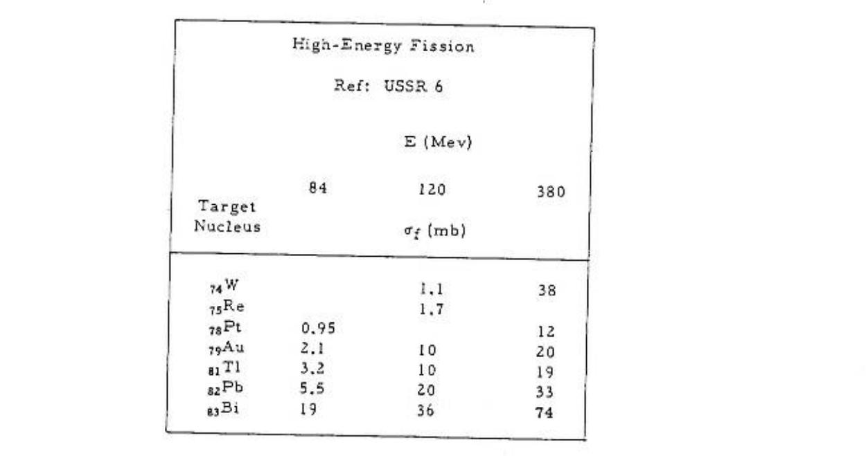
Media:high enegy fission x-section.jpg
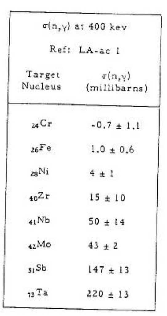
Media:N_gamma_x-section_at_400_keV.jpg
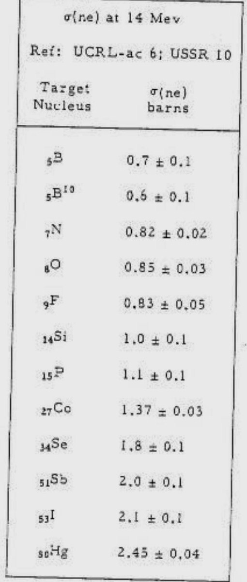
Media:x-sections of reactions at 14 MeV.jpg
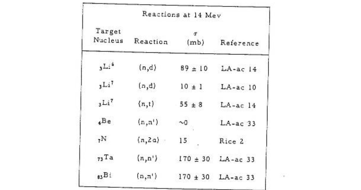
Media:n p x-section at 14.3MeV.jpg
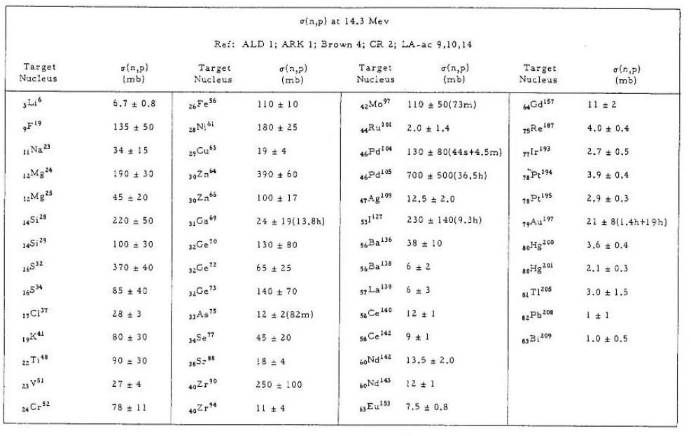
Media: n gamma x-section at 14.5 MeV.jpg
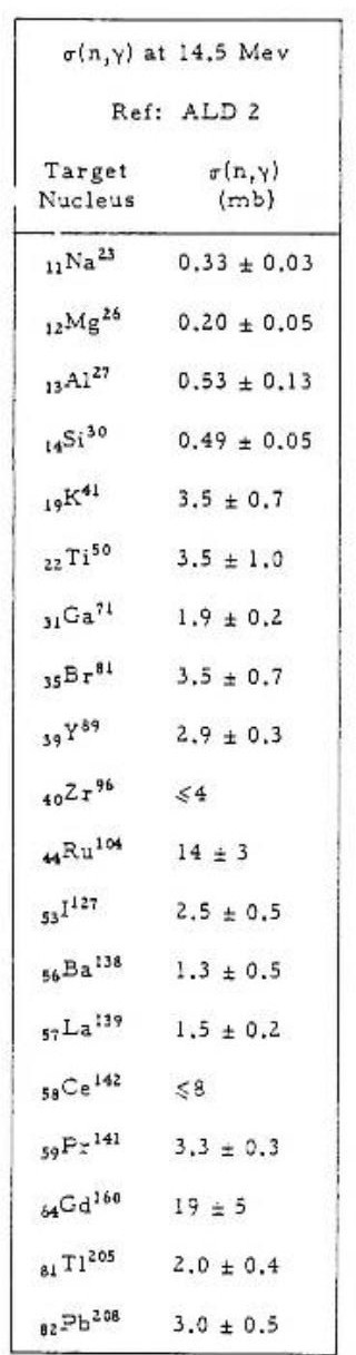
Media: elastic x-section at 0.5 MeV.jpg
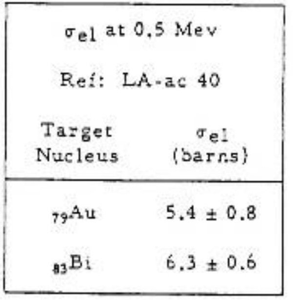
Media: n gamma x-section at 1 MeV.jpg
Media: n 2n x-section at 14.3 MeV.jpg
Donald James Hughes, Neutron cross sections, 2nd edition 1958, u.s.a atomic energy commission.Media:Neutron cross sections.pdf
File:NSAE 151 2005 319-334 Y.D. Lee.pdf
12 Volt power supply system.
http://www.lnf.infn.it/esperimenti/imagem/doc/NIMA_46128.pdf
http://electrontube.com.Media: rp097mono HV divier.pdf
http://www.cerac.com/pubs/proddata/thf4.htm#anchor550078
http://en.wikipedia.org/wiki/PC_board
RETGEMs
Media:Jinst8_02_p02012_THGEM_spark.pdf
Media: Nucl_Phys_B_Bidault_ novel UV photon detector.pdf
Media:Mauro micro pattern gaseuos detectors.pdf
Media:Development and First Tests of GEM-Like Detectors With Resistive Electrodes.pdf
http://www.supplydivision.co.uk/genitem.htm
Ideas
1.) Can we mix resistive paste (Encre MINICO) with TH-232. We construct a "bed of nails" to place a predrilled G-10 board with a copper border. The nails fill in the holes of the G-10 to keep the paste out. Ecre MINICO is a resistive paste used for transistors.
a.) Get some resistive paste.
http://www.leggesystems.com/p-253-elimstat-uxm-ccp.aspx
Resistive glue to compare
http://www.ellsworth.com/conformal.html?tab=Products
http://www.ellsworth.com/display/productdetail.html?productid=764&Tab=Products
http://www.ellsworth.com/display/productdetail.html?productid=2067&Tab=Products
http://www.cotronics.com/vo/cotr/ea_electricalresistant.htm
b.) mix with a metal similar to Th-232.
c.) construct bed of 0.4 mm nails. Look for 0.4 mm diameter pins.
7/31/2009
New vendor for carbon paste.
http://www.electrapolymers.com/productItem.asp?id=33
The data sheet does not show any information about the thickness of the paste.File:ED7100 Series paste.pdf
The company has a distributor in the usa (877)-867-9668. A phone call is expected on Sat. 8/3/2009 about the availability of the product.
TGEM Mask Design
Coating U-238 or Th-232 is essential for neutron detection in the range 2-14 MeV, but THGEM contains holes that should be protected from any coating material. So, a mask is designed to cover these holes. The holes are in drilled to be on the corners of hexagonal of 1mm side length as in the figure:

The mask is made of stainless steel, 10 um laser tolerance with cut the plate to get the shape in the figure:

Please look at the following files for more details:
Make number bold black font. Add color so it is clear that they are holes in a material.