Difference between revisions of "Mini-prototype"
| Line 168: | Line 168: | ||
== Translator Board NIM Module == | == Translator Board NIM Module == | ||
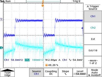
| − | The DC preamp output is sent to a translator board in a NIM bin module. The translator board takes the differential preamplifier output as input and outputs a single ended pulse through the front panel lemo connectors. A | + | The DC preamp output is sent to a translator board in a NIM bin module. The translator board takes the differential preamplifier output as input and outputs a single ended pulse through the front panel lemo connectors. A 100 mV negative test pulse was injected into the preamplifier board and sent to all preamp channels. The output of the translator board was looked at on a scope and compared to the preamp input pulse. The image below shows the input pulse to the drift chamber preamp circuit via the lemo input on the top trace and the translator output on the bottom trace. All signals were terminated in 50 Ohms on the scope. |
[[Image:Plastika_TranslaterBoardOutput_11-15-07.jpg | 400 px]] | [[Image:Plastika_TranslaterBoardOutput_11-15-07.jpg | 400 px]] | ||
Revision as of 23:12, 21 November 2007
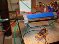
Drift Chamber prototypes were constructed to evaluate drift chamber designs for CLAS12.
Run Plan for Mini-prototype Performance Measurements
Description of General Operation
Chamber Ionization Gas
Our initial plan will be to use (75/25) flowing though the chamber at a flow rate high enough to exchange the volume once a day.
high Voltage supply
A CAEN 4 channel high voltage supply (N470) will be used to supply HV to the drift chambers. The supply is capable of monitoring currents at the microAmp(A) level and voltages at the Volt (V) level.
An e-mail from Mac has suggested we run the chamber such that the voltage difference between the sense and field wire be about 2490 Volts. He suggests sense:field:guard voltages of 1660:-830:830 respectively as a starting point and recommends keeping the ratio 2:-1:1 in order to have equal gain among the sense wires.
Signal Processing
Each sense wire is capacitively coupled to a preamplifier by a 221 pF capacitor. A schematic of the preamplifier (CP01H1- Hybrid) is shown below.
File:MiniProtoDC PreamplifierCircuit.pdf
File:MiniProtoDC BFT25.pdf
File:MiniProtoDC BFT92.pdf
a signal translator board was designed to power the 7 preamplifiers for each sense wire. A negative voltage regulator (Fairchild part # LM7905CT File:MiniProtoDC VoltageReg LM790CT.pdf) is used to regulate the +5 voltage voltage input thereby "floating" the ground of the circuit. The layout of this board is shown below.
File:MiniProtoDC SignalTranslatorBoard.pdf

The 7 sense wire signals from the Drift Chambers signal translator board will be processed through several
NIM based modules.
One can expect to amplify the sense wire output from a factor of 10 to 30 times. We will use our
Ortec amplifier to amplify the
sense wire output by a factor of 10.
A descriminator from Lecroy with a threshold range from 30 mV up to 1.5 Volts will be used to create a stop pulse for TDCs
that are started by scintillators which detect either an electron, during tests at the IAC, or cosmic rays, during tests at the LDS (see below). Hall B has loaned the ISU group a
TDC module for the drift chamber studies. Pulse height studies may also be done using an ADC. The DAQ system to manage the signal processing electronics is described below.
DAQ System
The DAQ system is described here
Cosmic tests
Apparatus
Place chamber between two plastic scintillator paddles to check signals. We will use the large area 7 cm by 50 cm paddles with the Russian PMTs operating at 1300 V and threshold > 150 mV to select energetic cosmic rays. We will arrange the paddles so that they are perpendicular to one another. From above, the paddles will have 7 cm by 7 cm overlap. This will allow for testing the chamber along its length.
scope pulses
We will insert oscilloscope pictures of the Drift Chamber output signals we observe.
Planned tests
We will use the scintillator paddles to detect cosmic rays and perform the following tests:
1. Efficiency along length of chamber with overlapping array of scint. paddles optimized for normal incidence.
2. Efficiency as a function of discriminator threshold, i.e. what is the required energy of the cosmic ray.
3. Efficiency as a function of angle. Count rates will decrease so we will have to determine the best overlapping configuration of the paddles.
4. Noise Rates. Generate a delayed OR gate from the two cosmic ray detectors in order to measure noise in the baby chamber. Record pulse heights on all wires + scintillators.
The above tests will give us a baseline for the drift chamber and are not designed to evaluate the efficiency as a function of distance from the endplate due to the large angular divergence of the incident cosmic rays and the limited counting statistics. We will use a finely collimated secondary electron beam at the IAC in order to make precision measurements of the efficiency as a function the ionization event distance from the endplate.
Electron test facility
IAC 25 MeV electron accelerator
The Idaho Accelerator Center (IAC) operates a 25 MeV Linac capable of delivering instantaneous electron currents of 80 mA/pulse. Pulse widths range from 80 ns to 2 s and repetition rates from single shot to 1 kHz. Drift Chamber testing will use this accelerator to create a secondary electron beam as described below.
secondary electron beam setup
We will need to bring the electron beam from Accelerator lab #1 to the experimental testing cell labeled as "target room" .
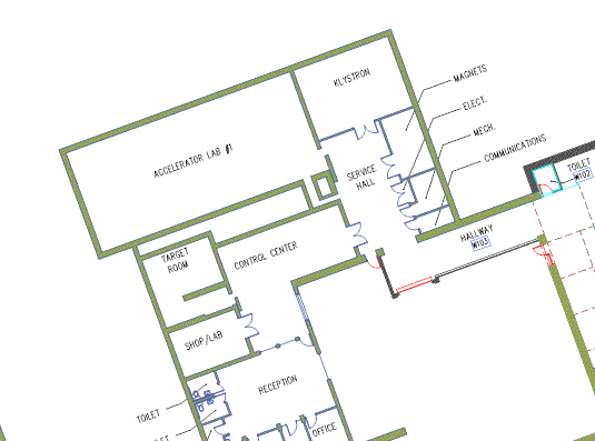 Floor Plan of IAC.
An evacuated beam pipe from the current exit window of the LINAC to the collimator entrance at the wall will be built to accomplish this. Magnetic elements are already in place to stear electrons into the "target room". The pipe will have aluminum windows at either end to allow for passage of the electron beam. Phil will be responsible for the design and safety concerns of implementing the pipe. The wall is 6' thick, which is 4' of packed earth sandwiched between 1' of concrete on either side. Upon reaching the wall the electron beam will travel through the hole defined by the collimator aperture. The electron beam will have to travel through a distance of 8' of air as it goes into the experimental test cell. The radiation length of air at STP is over 300 m, so this ought not be a problem. We can place an insert into the collimator on the test cell side to define the electron beam if need be.
We will use Dan's idea of elastic scattering. See: http://www.physics.isu.edu/~cole/IAC/DC_prototype/Detector-Test.pdf
The idea: the beam is incident upon a pencil lead target and the electrons will elastically scatter off the carbon atoms. The prototype will be positioned perpendicular to the incident electron beam so that only the elastically scattered electrons will pass through the chamber. We will place 5 mm by 5 mm scintillators on either side of the chamber. This scintillator arrangement allows for triggering and defining the beam. The paddles will be fixed and the prototype will be on a moveable platform that will be controlled by a stepper motor. This will allow us to measure the sense wire efficiency along the length of the wire and, in particular, the efficiency in close proximity to the feedthroughs.
Description of how beam size will be measured or why it isn't needed.
stepper device
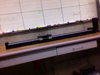
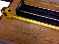
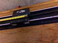
I think the device below can be used to move the minichamber across the backscattered electron beam. The device is over 3 feet in length and has a platform with is 6" x 6". We should configure the platform so it can hold both chambers "back-to-back" in order to test both chambers at the same time. The first chamber has four 3/8" bolts on the bottom for mounting but the 2nd one has yet to have anything.
Drift Chamber efficiency measurements
Efficiency -vs- Distance
The secondary electron beam will be moved towards the drift chamber endplate while the efficiency is measured. The results of our tests will be placed below.
| Distance | Feedthrough Efficiency | |
| (mm) | plastic | metal |
| 2 | ||
| 4 | ||
| 6 | ||
| 8 | ||
| 10 | ||
| 12 | ||
| 14 | ||
Metal feedthrough
Radiation Tests on Gas
Place chamber in main hall and direct high current electrons through the prototype.
1. Do not flush gas. How long does it take before the efficiency detiorates due to radiation damage of the gas.
2. Flush gas at variable rates to determine what the minimum flush rate is to ascertain proper stable efficiency.
Measurements in LDS
HV connections and Readout
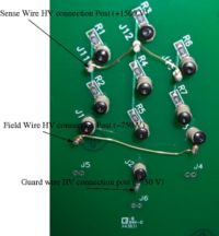
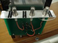
The High Voltage lines are shown below along with labels for the three voltages. I will try to install SHV connectors as well as a plastic safety shield to keep a student's finger away from the HV.
After Installing SHV BNC connectors
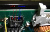
Preamp power connector inputs
Output connector. Preamp output signals are differential.
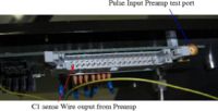
Inspecting Detector Signals
The sense wire drift chamber output was monitored to search for ionization events from cosmic rays. A scintillator paddle was place on top of the detector in order to create a scope trigger which would indicate the passage of a charged particle.
The link below describes scope measurements taken in the LDS
Preamp Output
The preamplifiers described above are capacitively connected to the sense wires using the custom built signal translator board. I applied 5.7 to 6.0 Volts to the board based on observations using a test pulses input to the signal board. Under operating conditions a RC like feedback noise with an MHz frequency and 50 mV amplitude was observed as the voltage to the preamp board is increased from about 2.8 volts to 5.5 volts. The link below documents our observations.
The next step will be to setup the DAQ system to perform to measure the sense wire outputs. I will use the cosmic telescope to generate a trigger pulse when cosmic rays pass through the drift chamber. When we install the system up at the IAC the beam RF will be used as the trigger.
Determining Min operating HV
The output of all seven sense wires was measured using a scope in order to identify the high voltage settings to be used when operating the drift chamber.
Translator Board NIM Module
The DC preamp output is sent to a translator board in a NIM bin module. The translator board takes the differential preamplifier output as input and outputs a single ended pulse through the front panel lemo connectors. A 100 mV negative test pulse was injected into the preamplifier board and sent to all preamp channels. The output of the translator board was looked at on a scope and compared to the preamp input pulse. The image below shows the input pulse to the drift chamber preamp circuit via the lemo input on the top trace and the translator output on the bottom trace. All signals were terminated in 50 Ohms on the scope.
