Difference between revisions of "GEM and Mini Prototype DC Cosmics Run"
| Line 130: | Line 130: | ||
|1550 || r693 || || | |1550 || r693 || || | ||
|- | |- | ||
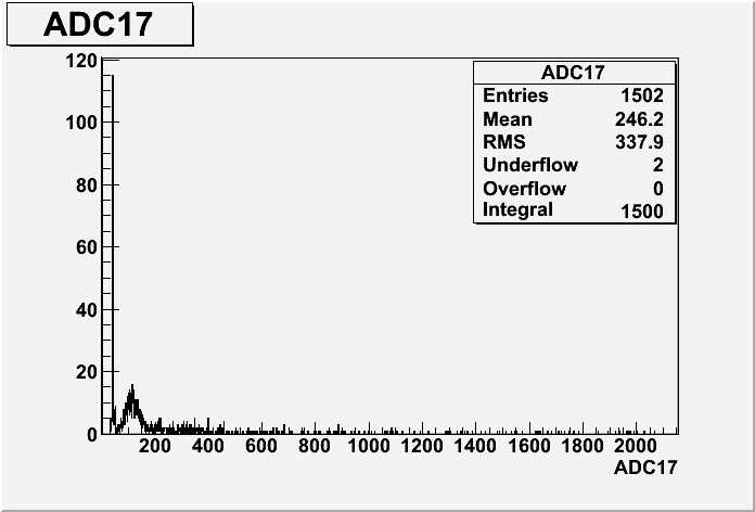
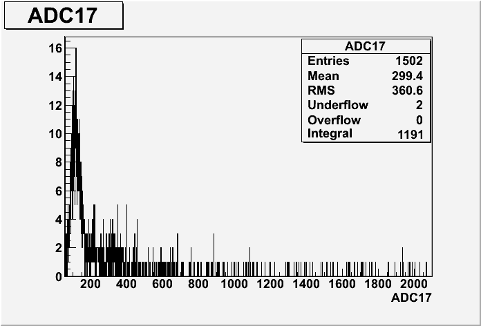
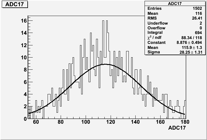
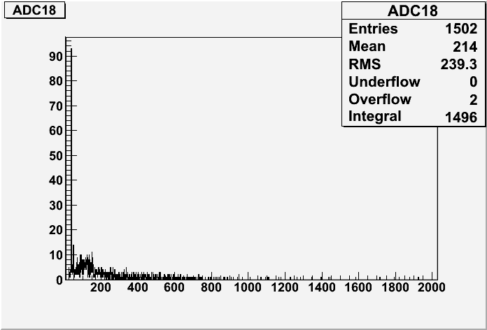
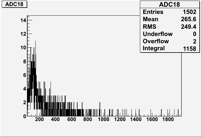
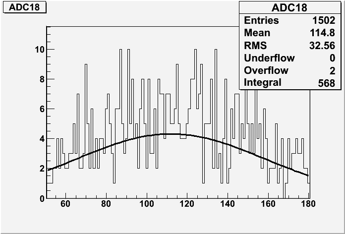
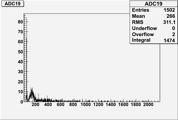
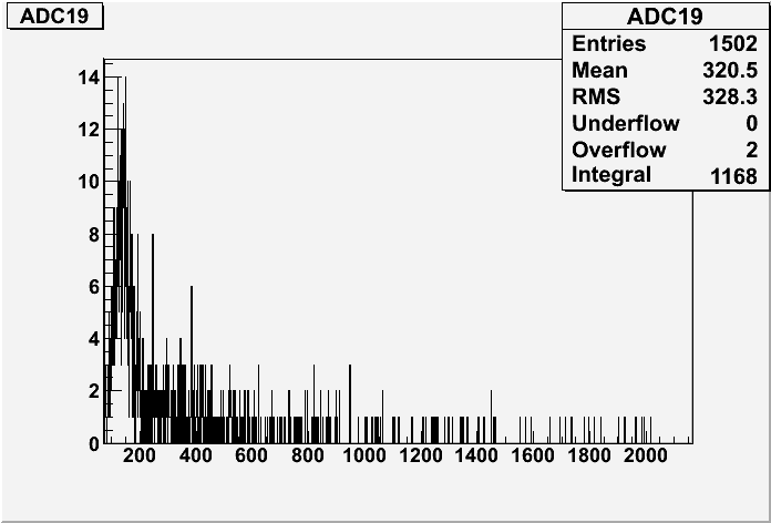
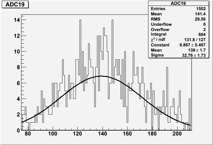
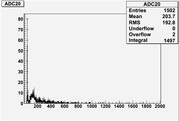
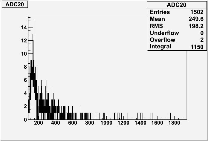
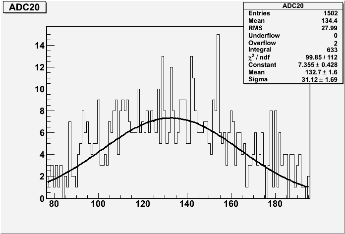
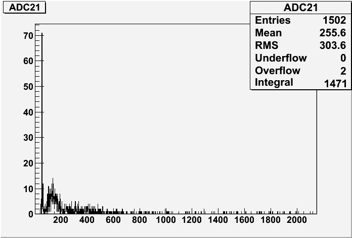
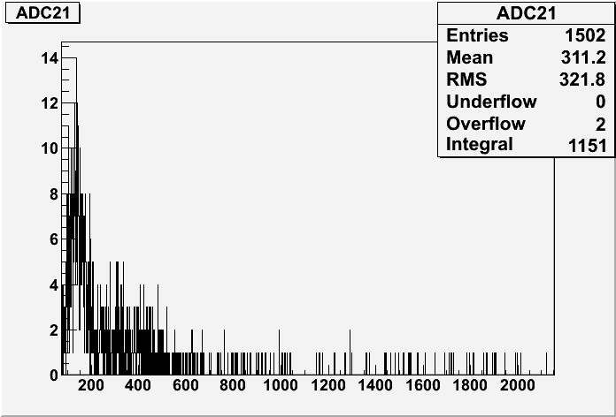
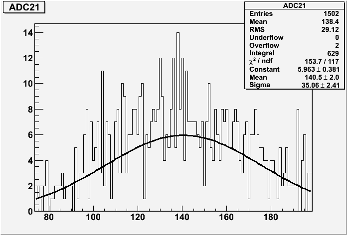
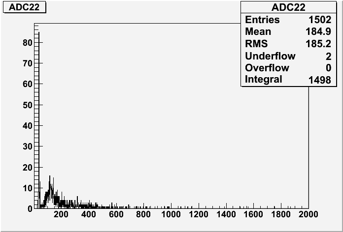
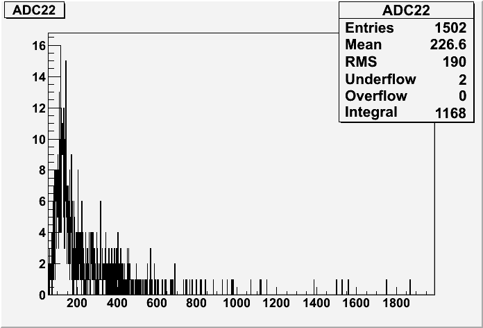
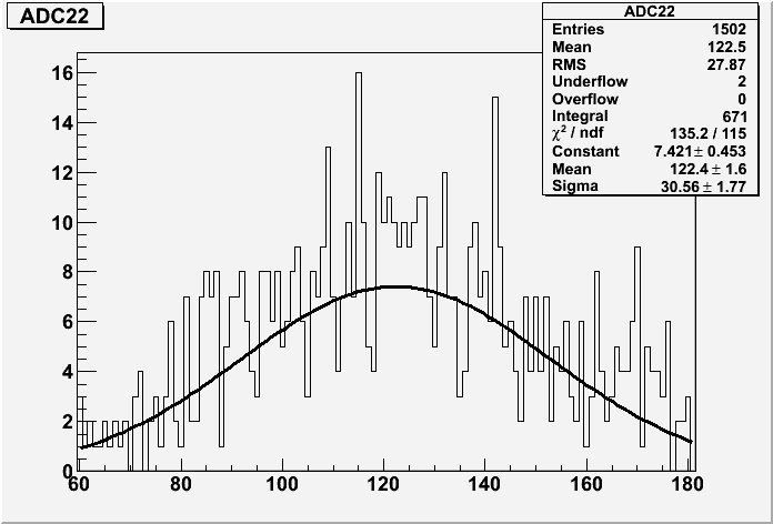
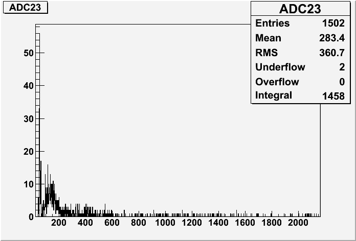
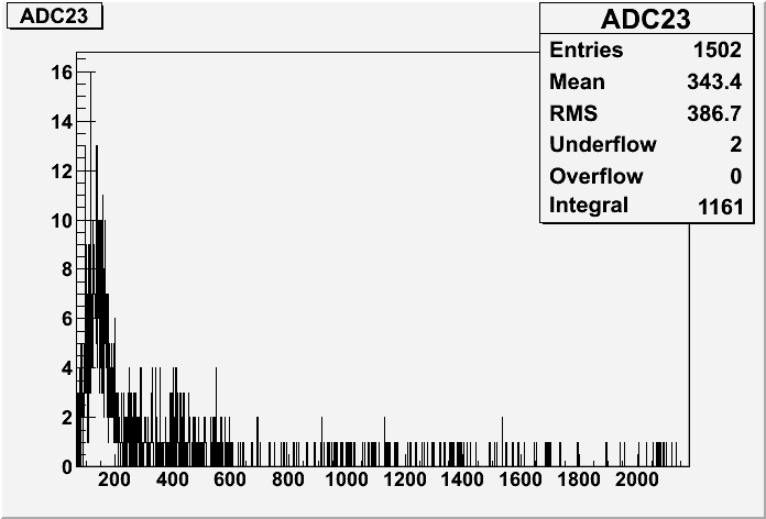
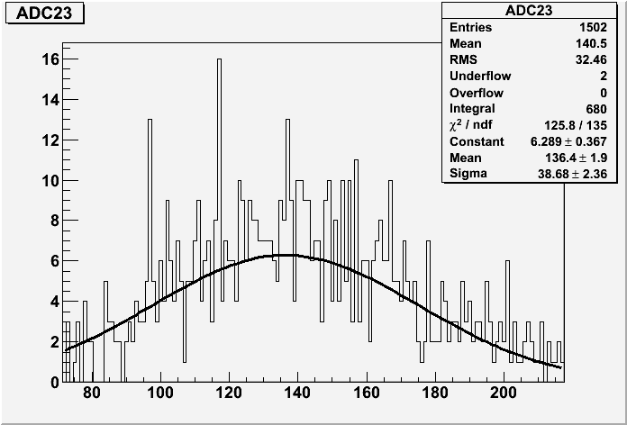
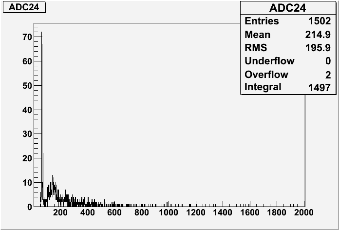
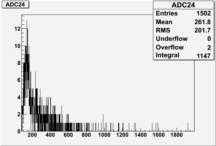
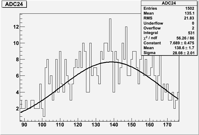
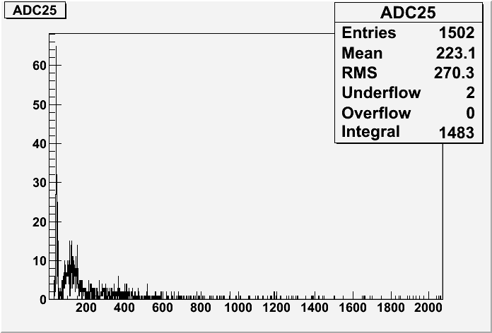
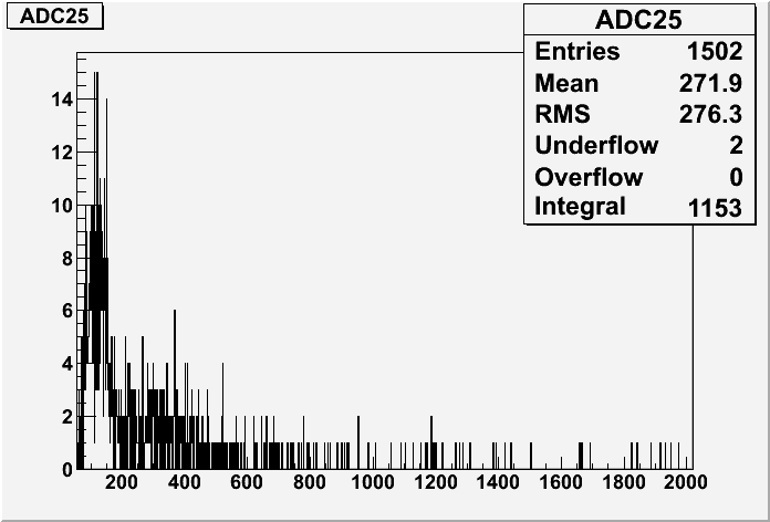
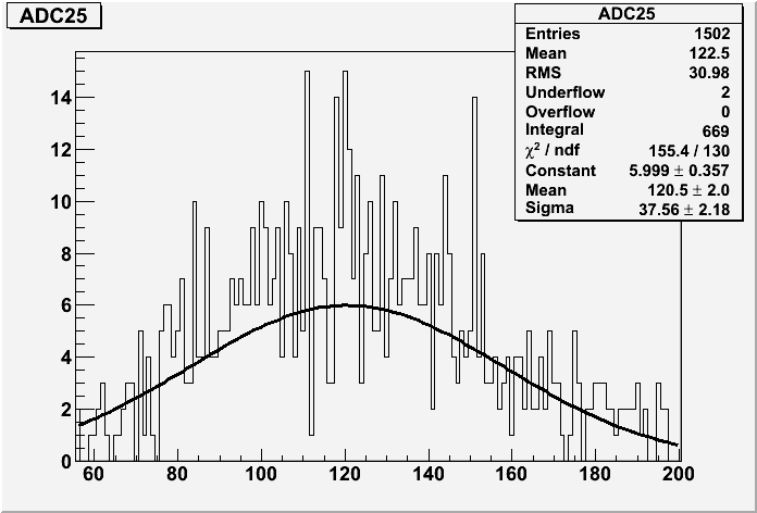
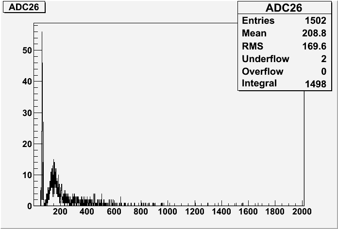
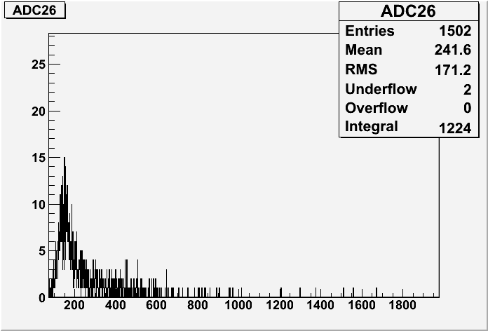
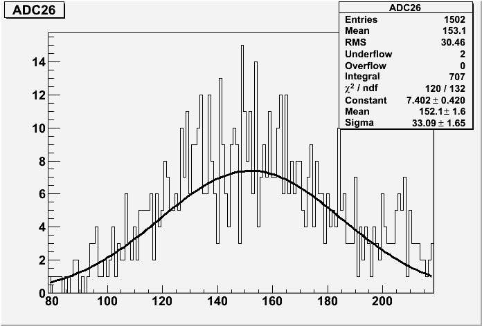
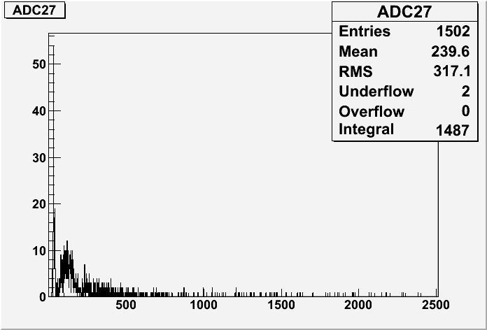
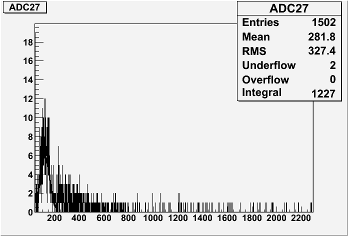
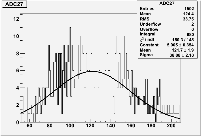
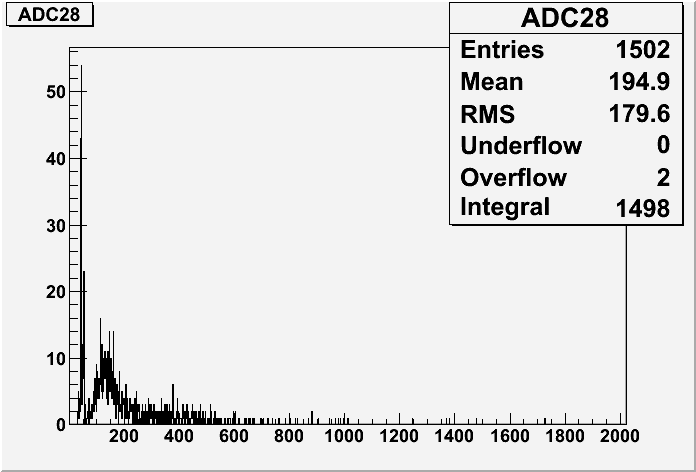
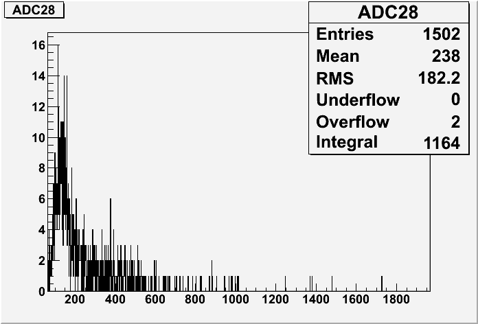
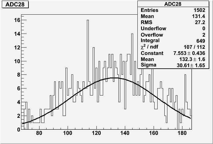
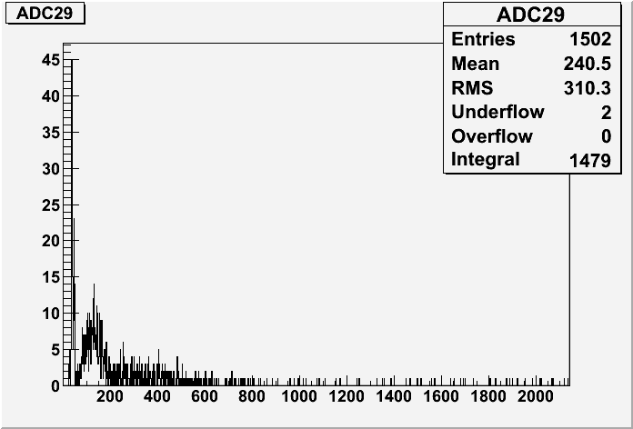
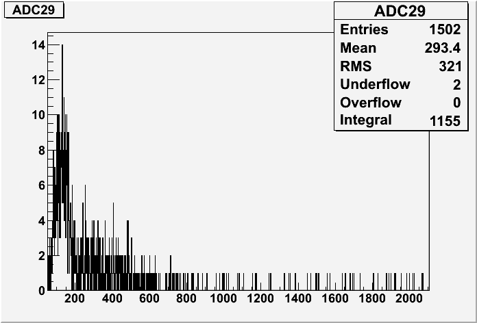
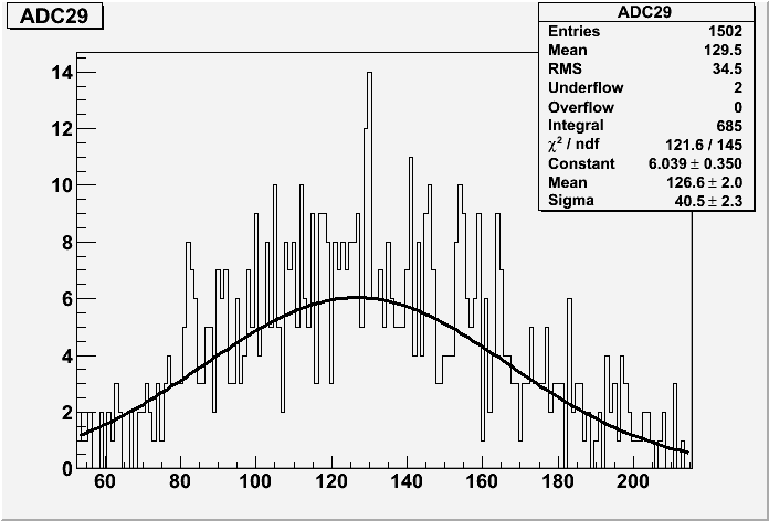
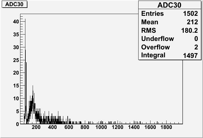
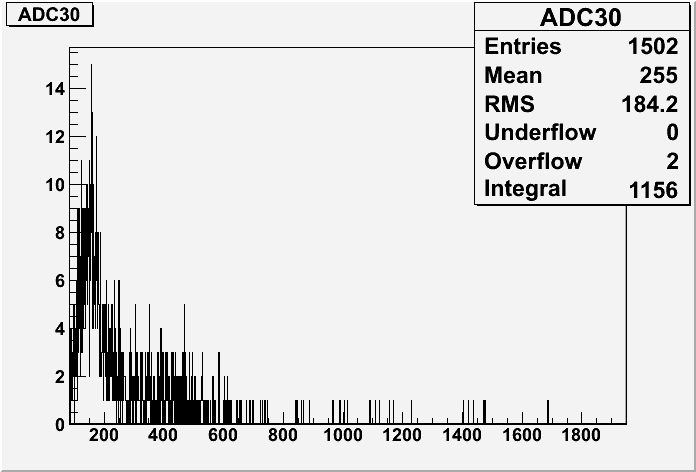
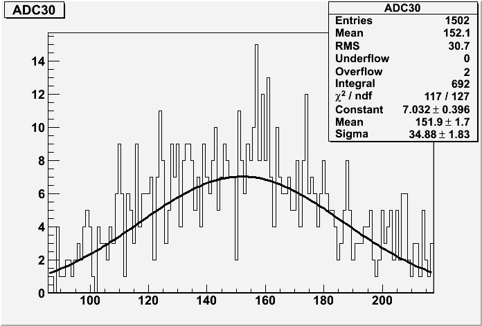
| − | | 1500 || r691 ||[[Image:r691_ ADC17_tot.gif]] || [[Image: | + | | 1500 || r691 ||[[Image:r691_ ADC17_tot.gif]] || [[Image:r691_ADC17_peak.gif]] ||[[Image:r691_ADC17_gaussian_fit.gif]] || [[Image:r691_ADC18_tot.gif]] || [[Image:r691_ADC18_peak.gif]] || [[Image:r691_ADC18_gaussian_fit.gif]] || [[Image:r691_ADC19_tot.gif]] || [[Image:r691_ADC19_peak.gif]] || [[Image:r691_ADC19_gaussian_fit.gif]] || [[Image:r691_ADC20_tot.gif]] || [[Image:r691_ADC20_peak.gif]] || [[Image:r691_ADC20_gaussian_fit.gif]] || [[Image:r691_ADC21_tot.gif]] || [[Image:r691_ADC21_peak.gif]] || [[Image:r691_ADC21_gaussian_fit.gif]] || [[Image:r691_ADC22_tot.gif]] || [[Image:r691_ADC22_peak.gif]] || [[Image:r691_ADC22_gaussian_fit.gif]] || [[Image:r691_ADC23_tot.gif]] || [[Image:r691_ADC23_peak.gif]] || [[Image:r691_ADC23_gaussian_fit.gif]] || [[Image:r691_ADC24_tot.gif]] || [[Image:r691_ADC24_peak.gif]] || [[Image:r691_ADC24_gaussian_fit.gif]] || [[Image:r691_ADC25_tot.gif]] || [[Image:r691_ADC25_peak.gif]] || [[Image:r691_ADC25_gaussian_fit.gif]] || [[Image:r691_ADC26_tot.gif]] || [[Image:r691_ADC26_peak.gif]] || [[Image:r691_ADC26_gaussian_fit.gif]] || [[Image:r691_ADC27_tot.gif]] || [[Image:r691_ADC27_peak.gif]] || [[Image:r691_ADC27_gaussian_fit.gif]] || [[Image:r691_ADC28_tot.gif]] || [[Image:r691_ADC28_peak.gif]] || [[Image:r691_ADC28_gaussian_fit.gif]] || [[Image:r691_ADC29_tot.gif]] || [[Image:r691_ADC29_peak.gif]] || [[Image:r691_ADC29_gaussian_fit.gif]] || [[Image:r691_ADC30_tot.gif]] || [[Image:r691_ADC30_peak.gif]] || [[Image:r691_ADC30_gaussian_fit.gif]] |
|- | |- | ||
| 1450 || r692 || || 796/1049 = 0.759 | | 1450 || r692 || || 796/1049 = 0.759 | ||
Revision as of 03:29, 19 January 2009
12-22-08
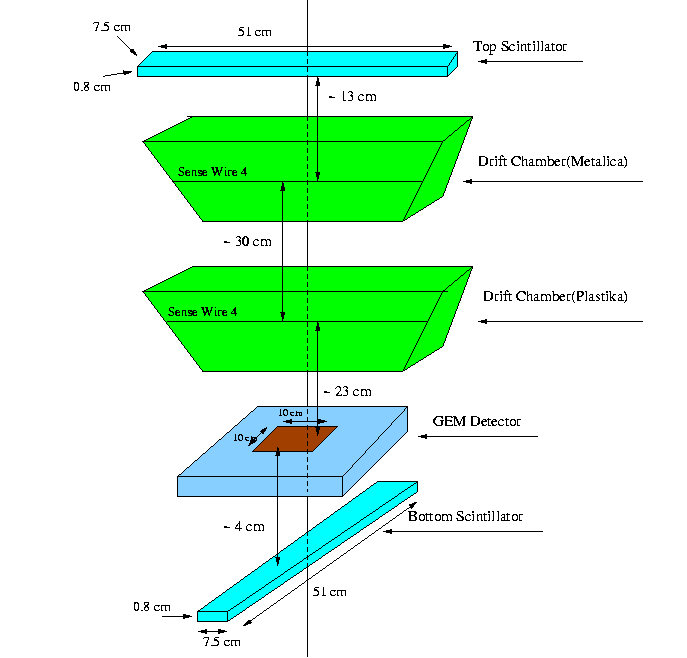
- Experimental Setup
- Tables
For Metalica
| Metalica Sense Wire # | VPI PostAmplifier Output(ADC && TDC) | ADC Channel# (VME) | TDC Channel# (VME) |
| 1 | 16 | 17 | 1 |
| 2 | 14 | 19 | 3 |
| 3 | 12 | 21 | 5 |
| 4 | 10 | 23 | 7 |
| 5 | 8 | 25 | 9 |
| 6 | 6 | 27 | 11 |
| 7 | 4 | 29 | 13(no cable) |
For Plastika
| Plastika Sense Wire # | VPI PostAmplifier Output(ADC && TDC) | ADC Channel# (VME) | TDC Channel# (VME) |
| 1 | 15 | 18 | 2 |
| 2 | 13 | 20 | 4 |
| 3 | 11 | 22 | 6 |
| 4 | 9 | 24 | 8 |
| 5 | 7 | 26 | 10 |
| 6 | 5 | 28 | 12 |
| 7 | 3 | 30 | 14(not connected) |
Setting Electronics
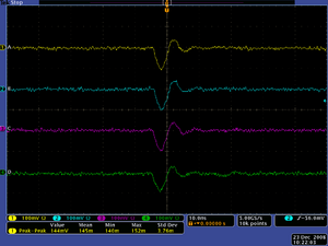
Using The Stanford Pulse Generator, Model DG535, four identical pulses were injected into the GEM(I mean output),, two PMTs and DC(first Metalica and then Plastika).
12-23-08
Mini DCs and GEM detectors are sandwiched between the two PMTs. The top scintillator is operated at 1050 Volts and bottom one-1000 Volts.
HV settings on GEM detector: Volts and Volts
HV settings on DCs: Sense=1450 Volts, Field=-725 Volts && Guard=724 Volts.
The coincidence pulse from two PMTs is used as a trigger and gate for GEM and DCs.
The PreAmp voltage on DCs is set to 6.4 Volts, the pulse form DC is amplified using PostAmplifier(amplification is on maximum). The TDC output of the amplified pulse is discriminated using the Leading Edge Discriminator and putted to the NIM-ECL converter, which than goes to the TDC(VME). The ADC output of the PostAmp was used for ADC(VME).
Run Number is r685
1-5-08
The GEM ADC measurements from the last cosmic run do not show a GEM signal while the DC has a clear ADC signal. Is the GEM output in time with the ADC gate?
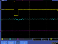
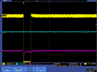
I only saw one GEM signal from Trig out when triggering the scope on the bottom scintillator. It looked like
Some drift chamber signals start hat before the gate suggesting there is too much delay on the gate line.
I observed more DC signals from channel 7 than GEM trigger signals when I triggered the scope on the bottom scintilator. Could the GEM gain/efficiency be substantially lower than the DC?
- When running with HRRL electrons we should probably set the HV for each detector so they have the same rate.
Changed integrate gate from 150 ns to 300ns
Increased GEM HV 25 volts from 3325/2925 to 3350/2950
1-6-09
starting cosmic run # 686 on Jan 6 17:54.
- Next week let's do plateau measurements, change HV and measurements cosmics for 1 day to plot rate -vs- voltage
- Mac will double check his calculations for the correct sense wire HV.
1-12-09
Plateau measurements
| HV settings on Sense Wire (Volts) | Run Number | Run Period | ADC23 Signal Counts/scint trigger" |
| 1500 | r691 | 1201/1502 = 0.800 | |
| 1450 | r692 | 796/1049 = 0.759 | |
| 1400 | r696 | 1089/1477 = 0.737 |
- Histograms for Each ADC
1-14-09
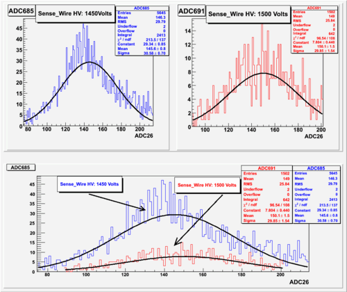
Comparison of two runs: r685_vsr691
The HV for Sense wire in run 685 was set to 1450 Volts and for 691 - 1500 Volts
[1] Go back
Mini-prototype
