G4Beamline PbBi
Development of a Positron source using a PbBi converter and a Solenoid
Conclusions
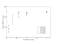
- A 0.3 (0.6) Tesla Solenoid with a diameter to allow a 9.74 (3.94) cm diameter pipe would collect a positron per thousand incident electrons on a 2mm thick PbBi target with 0.125 mm thick SS windows.
- A 4 Tesla Solenoid will remove beam pipe heating from scattered electrons downstream of the target when using a 3.94 cm diameter beam pipe.
Reports
Task List
1.) Create a positron (10,000 positrons) and electron event file containing t,x,y,z,Px,Py,Pz for positrons exiting the solenoid and an incident Gaussian beam 1cm in diameter and with a sigma of 1cm.
compare distributions with and without solenoid.
2.) Determine the back ground when using a 3.48 diameter beam pipe and Solenoid field of 0.2 for a NaI detector placed at
3.) Experiment, install dipole and solenoid in the tunnel.
Beam Pipe Heating
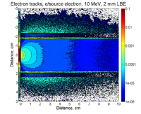
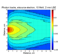
A 10 MeV electron beam with a radius of 0.5 cm was incident on a 2 mm thick PbBi target. The target is positioned at Z = -902 mm.
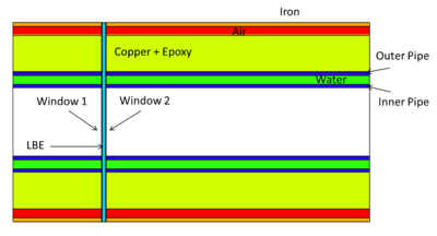
| Element | dimension |
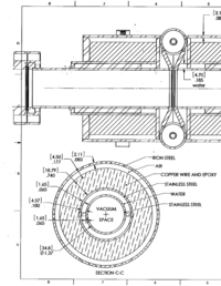
| Inner beam pipe radius | 1.74 cm |
| Inner beam pipe thickness | 0.165 cm |
| water jacket thickness | 0.457 cm |
| outer beam pipe radius | 2.362 cm |
| outer beam pipe thickness | 0.165 cm |
| Solenoid inner radius | 2.527 cm |
| Solenoid outer radius | 4.406 cm |
Max power deposited in beam pipe from uniform beam heating
If you assume a 1mA beam then the beam power incident on the target is
Beam Power = E(MeV) I ( A) = 10 MeV 1000 mA = 10 kW
If the beam does not interact with the target and all the beam power is distributed uniformly along a 100 cm long beam pipe with a diameter of 3.48 cm then the power deposited per area would be
A simulation predicts that about 8 out of 20 electrons will interact with the target and intercept a 34.8 mm diameter beam pipe surrounding the target.
BUT the beam does not intersect the pipe uniformly and instead can have a hot spot.
Heating along the Z-axis
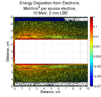
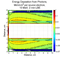
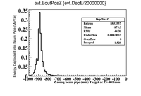
GEANT4 predicts that scattered electrons, photons, and positrons (mostly scattered electrons) deposit
 |

|
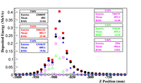
According to the above figure, GEANT4 predicts a total of MeV (the integral adds up the energy in each 1cm bin) of energy will be deposited in a 1m long beam pipe surrounding a 2 mm thick PbBi target located at Z=-902 mm when 20 million electrons impinge the target. The peak energy deposition is 0.3 MeV/e
If this energy were uniformly distributed along the 5 mm thick beam pipe having a diameter of 3.48 cm then I would see
if you assume a 1 mA beam of electrons then this becomes
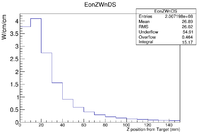
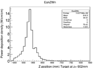
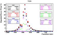
I converted the above histogram to deposited power by 1000 mA, divide by the number of incident electrons, divide by the circumference of the beam pipe, convert the number of electrons to Coulombs, and use a unit conversion from MeV to W-s per MeV.
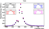
If you use the above factors to weight the histogram, then the figure below shows that GEANT4 predicts a power deposition density of , 1 cm downstream of the target. Back scattered electrons appear to create the hottest spot of about 1cm upstream of the target.
 |
|
| Power Deposition Zoomed in and 902 mm offset applied | Power deposition over the 1 m long beam pipe |
BeamPipeHeating_4mmthick_PbBi_PositronTarget
Unit conversion
The energy deposited by photon, electrons, and positrons is predicted by GEANT4 and recorded in energy units of keV per incident electron on the PbBi target. To convert this deposited energy to a power you need to assume a beam current. Assuming 1 beam current of 1 mA, the conversion is given easily as
Results Table
| Beam Pipe Diameter (mm) | Hot Spot () | Hot Spot () |
| 34.8 | 0.35 | |
| 47.5 | 0.24 | |
| 60.2 | 0.20 | |
| 72.9 | 0.16 | |
| 97.4 | 0.12 |
Converter target properties
Definition of Lead Bismuth
1cm diameter target
2 mm thick PbBi
0.5 Tesla solenoid
Desire to know
Emmittance (mrad * mm)
dispersion (Delta P/P) (mradian/1000th mm/1000th)
of electrons after the PbBi target.
pole face rotation in vertical plane.
G4BeamLine and MCNPX
Target thickness optimization
PbBi_THickness_GaussBeam
PbBi_THickness_CylinderBeam
PbBi_THickness_PntSource
Energy Deposition in Target system (Heat)
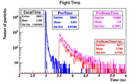
MCNPX simulations of energy deposition into different cells are below. There is a slight overestimate (they add up to about 120%). Positrons contribute less than 1% of electrons' contribution. No magnetic filed is assumed.
Solenoid
Uniform ideal Solenoid
Beam Pipe Heating with Solenoid
The energy deposited by electrons scattered into a 3.48 diameter stainless steel beam pipe (1.65 mm thick) from a PbBi target as a function of a uniform Solenoidal magnetic field.
| B-field (Tesla) | Hot Spot () |
| 0.0 | 0.35 |
| 0.3 | 0.35 |
| 1.0 | 0.35 |
| 1.5 | 0.22 |
| 2.0 | 0.10 |
| 4.0 | 0.002 |
To convert this deposited energy per incident electron on the target to a heat load in the pipe you need to divide by the area of the pipe.
A histogram is filled with 1 cm bins along the Z axis. The surface area becomes . The beam pipe diameter assumed is 3.48 cm.
When filling the histogram binned 1 cm in Z, you should weight it by the amount of depositred energy divided by the circumference of the pipe and divided by the number of incident electrons on the target (5 million). The energy units are converted to keV by multiplying the numberator by 100 or in this case dividing by 5000 instead of 5 million.
TH1F *T00N=new TH1F("T00N","T00N",100,-1000.5,-0.5)
Electrons->Draw("evt.EoutPosZ>>T00N","evt.DepE/10.088/5000")
To convert From Mev/ e- to kW/cm^2 assuming a current of 1mA (10^-3 C/s) you
 |
 |
|
With SS windows
Positrons->Draw("sqrt(evt.BeamPosPosX*evt.BeamPosPosX+evt.BeamPosPosY*evt.BeamPosPosY)","evt.BeamPosMomZ>0 && evt.BeamPosPosZ>-500 && sqrt(evt.BeamPosPosX*evt.BeamPosPosX+evt.BeamPosPosY*evt.BeamPosPosY)<97.4/2");
Positron Collection rates with 60 cm long Solenoid
With SS windows
Positrons->Draw("sqrt(evt.BeamPosPosX*evt.BeamPosPosX+evt.BeamPosPosY*evt.BeamPosPosY)","evt.BeamPosMomZ>0 && evt.BeamPosPosZ>-500 && sqrt(evt.BeamPosPosX*evt.BeamPosPosX+evt.BeamPosPosY*evt.BeamPosPosY)<97.4/2");
| B-field (Tesla) | 34.8 mm diameter pipe | 47.5 | 60.2 | 72.9 | 97.4 | |
| 0.0 | 0.35 | 1,2,4,4,5 | 2,3,4,4,6 | 4,4,6,7,9 | 6,8,9,10,11 | 16,14,15,16,17 |
| 0.1 | 225,236,250,246,249=241 10 | 282,282,293,294,306=291 10 | 373,366,370,364,373=369 4 | 451,437,440,438,451=443 7 | 602,584,563,558,570=575 18 | |
| 0.3 | 0.35 | 626,619,596,619,611 =614 11 | 720,726,706,730,717=720 9 | 871,864,840,841,834 =850 16 | 987,968,939,943,952 =958 20 | 1118,1106,1069,1067,1080=1088 23 |
| 0.6 | 929,935,949,969,961=949 17 | 1022,1031,1046,1059,1052 =1042 15 | 1120,1130,1152,1154,1146 =1140 15 | 1168,1184,1210,1221,1206 =1198 21 | 1212, 1218,1240,1254,1242=1233 18 | |
| 1.0 | 0.35 | 1117,1085,1083,1061,1085=1086 20 | 1188,1154,1140,1111,1134=1145 28 | 1225,1190,1178,1149,1172 =1183 28 | 1243.1208,1195,1164,1184=1199 30 | 1252,1219,1206,1178,1200=1211 27 |
| 1.5 | 0.22 | |||||
| 2.0 | 0.10 | 1198,1210,1215,1223,1176=1204 18 | 1216,1227,1235,1241,1196 =1223 18 | 1237,1243,1252,1257,1214=1241 17 | 1249,1252,1262,1266,1225 =1251 16 | 1257,1262,1270,1276,1234=1260 16 |
| 4.0 | 0.002 |
|
Positron & Electron event files
Event files were generated assuming an ideal solenoid having an inner radius of 2.527 cm surrounding a beam pipe with a radius of 1.74 cm. Electrons impinge a 2mm thick PbBi liquid target that has a surface area of 2.54 cm x 2.54 cm. Stainless steel windows 0.25 mm thick sandwhich the PbBi target at locations Z= -90.325 and Z= -89.875 cm. The target is located at Z =-90.1 cm and the beam begins 20 cm upstream at Z = -110.1 cm. The incident electron beam is a 0.5 cm radius cylinder.
Positrons exiting the Solenoid
The solenoid design has changed such that the max field is 0.20 Tesla (0.22) and its length is 150 mm.
In other words I should generate position and momentum files for positrons and electrons at the Z location 15 cm downstream from the middle of the LBE target and within a 3.48 cm diameter beam pipe.
/vis/viewer/zoom 2
/gps/pos/centre 0.0 0.0 -150.
/vis/viewer/panTo -90.1 0 cm
/vis/viewer/reset
Twenty (20) million incident electrons with an energy of 10 MeV and forming a cylindrical beam with a 0.5 cm radius cylinder impinged a 2mm thick LBE target located at Z = -106 mm. The Z location of positrons exiting the beam pipe at the end of the 15 cm long solenoid is 44 mm. The positrons are 150.00 mm from the middle of the LBE target (Z=44mm).
A space delimited text file with the above events in the format of
PID, x(mm),y,z,Px,Py,Pz(MeV),t(ns)
in units of cm for distance and MeV for momentum is located at
for positrons
http://www2.cose.isu.edu/~foretony/Positrons_2mm10MeVCyl.dat
and
http://www2.cose.isu.edu/~foretony/Electrons_2mm10MeVCyl.dat
The file below contains all the positrons that were created at the target
format
A space delimited text file with the above events in the format of
Initial electron (x,y,x,Px,Py,Pz), Final electron (t,x,y,z,Px,Py,Pz), Positron creation location (t,x,y,z,Px,Py,Pz),Location of positron outside the target (t,x,y,z,Px,Py,Pz).
http://www2.cose.isu.edu/~foretony/AllPositrons_2mm10MeVCyl.dat
Solenoid Map
Inner Radiusu=
Outer Radius =
Length =
Current=
Magnetic Field Map in cylindrical coordinates (Z & R) from Niowave
