Difference between revisions of "Sadiq BIW 2012"
| Line 9: | Line 9: | ||
= Abstract = | = Abstract = | ||
| − | + | A 16 MeV S-band linac at the Idaho Accelerator Center was recently reconfigured to produce a secondary beam of positrons by sending a 100 mA peak electron pulses onto a Tungsten converter. The transverse electron beam emittance was measured to determine the optimal configuration a quad triplet system used to capture the positrons escaping the downstream side of the Tungsten converter. In 2011, we developed a beam imaging system with a digital CCD camera, three optical lens, and an OTR screen for the emittance measurement. In this paper, we describe the hardware of our beam imaging system and its experimental results. | |
= Introduction = | = Introduction = | ||
Revision as of 04:30, 11 January 2012
Links
Abstract Submission to BIW2012
Imaging System for Emittance Measurement of IAC Medical Linac
Abstract
A 16 MeV S-band linac at the Idaho Accelerator Center was recently reconfigured to produce a secondary beam of positrons by sending a 100 mA peak electron pulses onto a Tungsten converter. The transverse electron beam emittance was measured to determine the optimal configuration a quad triplet system used to capture the positrons escaping the downstream side of the Tungsten converter. In 2011, we developed a beam imaging system with a digital CCD camera, three optical lens, and an OTR screen for the emittance measurement. In this paper, we describe the hardware of our beam imaging system and its experimental results.
Introduction
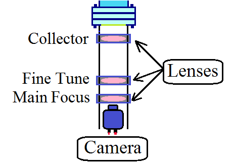
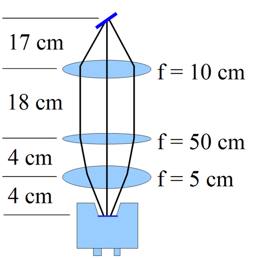
We used 3 lenses to collect OTR light from Al target. To improve image quality, 2 inch diameter lenses were selected. They have focal length of 100 mm, 500 mm and 50 mm, they were called collector lens, fine tune lens and main focus lens respectively. Collector lens has the middle focal length, collects most of the light from the source. Fine tune lens has the biggest focal length, act as fine tune of magnification. Main focus lens: has the smallest focal length, has biggest focusing strength, so act as main focus of light and focuses light to CCD.
Experiment Setup
Camera cage system was located below the OTR target. There are 3 lenses used to focus lights from target to the CCD camera. Target can be pushed into or taken out of the beamline by the actuator at the top.

