Lab 6 TF EIM
Lab 6 Pulses and RC Filters
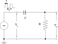
Differentiator
1.)Construct the circuit below selecting an RC combination such that RC s
2.) Adjust the pulse generator to output square pulses which at RC/10.
3.)Measure and . Sketch a picture comparing and .
4.) Change the pulse width such that RC
5.)Measure and .Sketch a picture comparing and .
6.) Change the pulse width such that=10 RC
7.)Measure and .Sketch a picture comparing and .
Questions
1.) What happens if than amplitude of is doubled.
2.) What happens if R is doubled and C is halved?
Integrator
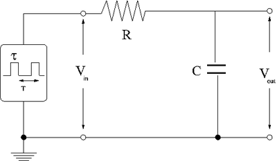
Now repeat the above experiment with the resistor and capacitor swapped to form the low pass circuit below.
Pulse Sharpener
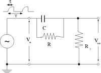
The goal of this section is to demonstrate how well the circuit below can sharpen an input pulse
1.) The first step is to create an input pulse which is rounded, similar to the output of the integrator circuit when RC = 10 .


