CED Verification of DC Angle Theta and Wire Correspondance
Note: According to DC geometry file the ced is off in its placement of wires.
The sense wires in any superlayer are arranged in an hexagonal pattern: each sense wire layer’s location is “half-cell staggered” such that the even sense wire layers (2,4,6) are shifted closer to the beam line than if the wire were arranged in a square layout. Colloquially speaking, the “zig-zag” direction for the six sense wire layers is “away,close,away,close,away,close”.
December 2016:CED Verification of DC Angle Theta and Wire Correspondance
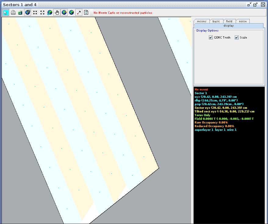
Using CED to verify the angle and wire correlation,
Zooming in on the view paralell to the direction of the wires in ced, we can examine the wire corresponding theta angle in the drift chamber.

| Coordinates(cm) | Layer 1 | Layer 2 | Layer 3 | Layer 4 | Layer 5 | Layer 6 |
|---|---|---|---|---|---|---|
| x | 20.42 | 21.51 | 21.39 | 22.49 | 22.37 | 23.47 |
| y | 0.00 | 0.00 | 0.00 | 0.00 | 0.00 | 0.00 |
| z | 243.41 | 244.18 | 245.51 | 246.28 | 247.62 | 248.38 |
| Coordinates(cm) | Layer 1 | Layer 2 | Layer 3 | Layer 4 | Layer 5 | Layer 6 |
|---|---|---|---|---|---|---|
| x | 21.64 | 22.73 | 22.61 | 23.71 | 23.58 | 24.69 |
| y | 0.00 | 0.00 | 0.00 | 0.00 | 0.00 | 0.00 |
| z | 242.86 | 243.62 | 244.94 | 245.71 | 247.05 | 247.81 |
Corresponding theta angles can be found for other wires, in Region 1, Superlayers 1 and 2.
| Wire Number | Layer 1 | Layer 2 | Layer 3 | Layer 4 | Layer 5 | Layer 6 |
|---|---|---|---|---|---|---|
| 1 | 4.79 | 5.03 | 4.98 | 5.22 | 5.16 | 5.40 |
| 2 | 5.09 | 5.33 | 5.27 | 5.51 | 5.45 | 5.69 |
| 77 | 29.46 | 29.60 | 29.41 | 29.55 | 29.37 | 29.51 |
| 78 | 29.79 | 29.93 | 29.74 | 29.88 | 29.69 | 29.83 |
| 79 | 30.12 | 30.26 | 30.07 | 30.21 | 30.02 | 30.16 |
| 110 | 40.19 | 40.28 | 40.05 | 40.13 | 39.91 | 39.99 |
| 111 | 40.51 | 40.59 | 40.36 | 40.44 | 40.21 | 40.29 |
| 112 | 40.82 | 40.90 | 40.67 | 40.75 | 40.52 | 40.60 |
May 2017:CED Verification of DC Angle Theta and Wire Correspondance
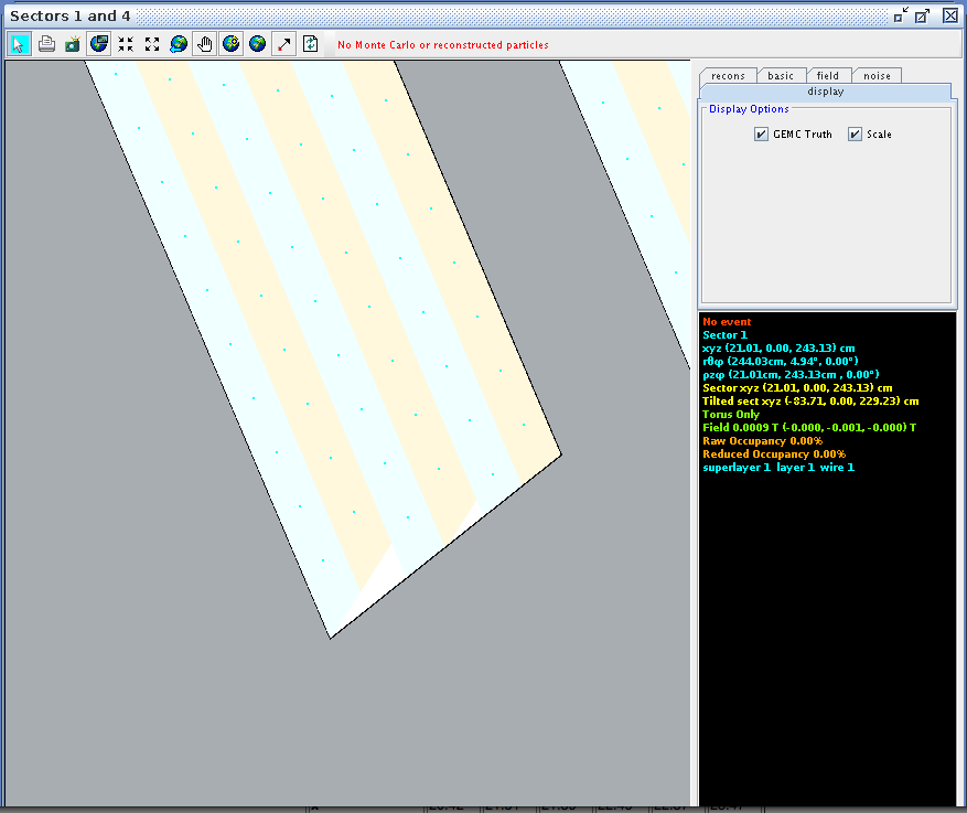
Using CED to verify the angle and wire correlation,
Zooming in on the view paralell to the direction of the wires in ced, we can examine the wire corresponding theta angle in the drift chamber.

| Coordinates(cm) | Layer 1 | Layer 2 | Layer 3 | Layer 4 | Layer 5 | Layer 6 |
|---|---|---|---|---|---|---|
| x | 21.01 | 22.11 | 21.98 | 23.08 | 22.95 | 24.07 |
| y | 0.00 | 0.00 | 0.00 | 0.00 | 0.00 | 0.00 |
| z | 243.13 | 244.89 | 245.23 | 245.99 | 247.33 | 248.12 |
| Coordinates(cm) | Layer 1 | Layer 2 | Layer 3 | Layer 4 | Layer 5 | Layer 6 |
|---|---|---|---|---|---|---|
| x | 22.23 | 23.32 | 23.20 | 24.29 | 24.17 | 25.29 |
| y | 0.00 | 0.00 | 0.00 | 0.00 | 0.00 | 0.00 |
| z | 242.55 | 243.32 | 244.68 | 245.42 | 246.75 | 247.55 |
Corresponding theta angles can be found for other wires, in Region 1, Superlayers 1 and 2.
| Wire Number | Layer 1 | Layer 2 | Layer 3 | Layer 4 | Layer 5 | Layer 6 |
|---|---|---|---|---|---|---|
| 1 | 4.95 | 5.18 | 5.12 | 5.36 | 5.30 | 5.55 |
| 2 | 5.24 | 5.48 | 5.42 | 5.65 | 5.60 | 5.84 |
| 77 | 29.62 | 29.76 | 29.57 | 29.71 | 29.53 | 29.67 |
| 78 | 29.95 | 30.09 | 29.90 | 30.04 | 29.85 | 29.99 |
| 79 | 30.28 | 30.42 | 30.23 | 30.36 | 30.18 | 30.32 |
| 110 | 40.35 | 40.42 | 40.19 | 40.28 | 40.05 | 40.13 |
| 111 | 40.66 | 40.74 | 40.51 | 40.59 | 40.36 | 40.44 |
| 112 | 40.96 | 41.04 | 40.81 | 40.89 | 40.66 | 40.75 |
Comparing with the calculated values with
| Wire Number | Layer 1 |
|---|---|
| 1 | 5.23 |
| 2 | 5.53 |
| 77 | 29.80 |
| 78 | 30.13 |
| 79 | 30.46 |
| 110 | 40.45 |
| 111 | 40.76 |
| 112 | 41.07 |