Difference between revisions of "Beam Test Jul 20 2012"
| (19 intermediate revisions by the same user not shown) | |||
| Line 1: | Line 1: | ||
We started up the accelerator where we left from yesterday. | We started up the accelerator where we left from yesterday. | ||
| + | |||
| + | = Tune = | ||
| + | |||
| + | |||
| + | |||
| + | {| border="1" | ||
| + | | Energy Switch || Out (High En) | ||
| + | |- | ||
| + | | Solenoid 1 || 6.1 A | ||
| + | |- | ||
| + | | Solenoid 2 || 3.2 A | ||
| + | |- | ||
| + | | Gun Hor || -0.2 A | ||
| + | |- | ||
| + | | Gun Ver || 0 A | ||
| + | |- | ||
| + | |Output Hor || -0.3 A | ||
| + | |- | ||
| + | | Output Ver || 0 A | ||
| + | |- | ||
| + | | Rep Rate || 8 | ||
| + | |- | ||
| + | | Gun HV || 10 (Knob Setting) | ||
| + | |- | ||
| + | | Gun Grid Voltage || 2.85 (Knob Setting) | ||
| + | |- | ||
| + | | RF frequency ||2856.310 MHz | ||
| + | |- | ||
| + | | Modulator HV Power Supply || 4.28 (Knob Setting) | ||
| + | |- | ||
| + | | RF macro Pulse Length (FWHM) || 300 ns | ||
| + | |- | ||
| + | |Q1 (A)|| -3.7 | ||
| + | |- | ||
| + | |Q2 (A)|| -5.5 | ||
| + | |- | ||
| + | |Q3 (A)|| +0.6 | ||
| + | |- | ||
| + | |} | ||
= Detector tests = | = Detector tests = | ||
== Beam Left Detector == | == Beam Left Detector == | ||
| + | |||
| + | Beam left detector is at 14.5 cm from the edge of the 6-way cross. Beam right detector is pushed right next to the edge of the 6-way cross. | ||
Electron gun trigger and detector diode signal put into and logic. We want to put the annihilation target in and out, see how it affects the rate. | Electron gun trigger and detector diode signal put into and logic. We want to put the annihilation target in and out, see how it affects the rate. | ||
| − | Annihilation Target Slit width | + | quad settings after T1 (Target 1, positron production target). |
| − | in 1.00 cm | + | q4 q5 q6 q7 q8 q9 q10 |
| − | out 1.00 cm | + | -0.0 +0.5 +0.0 +0.0 -1.0 -0.0 +0.0 |
| − | in 1.00 cm | + | |
| − | out 1.00 cm | + | Mode Annihilation Target Slit width D1(A) D2(A) Counts / Time(s) Rate(Hz) |
| − | out 0.20 cm | + | e+ in 1.00 cm 4.2 4.2 445 / 199.9 2.2 |
| − | in 0.20 cm | + | e+ out 1.00 cm 4.2 4.2 545 / 199.9 2.7 |
| + | e+ in 1.00 cm 4.2 4.2 241 / 99.8 2.4 | ||
| + | e+ out 1.00 cm 4.2 4.2 268 / 99.9 2.7 | ||
| + | e+ out 0.20 cm 4.2 4.2 692 / 200 3.5 | ||
| + | e+ in 0.20 cm 4.2 4.2 1178 / 199.9 5.9 | ||
| + | e+ in 0.20 cm 4.2 5.8 724 / 200 3.6 | ||
| + | e+ out 0.20 cm 4.2 5.8 1175 / 299.9 3.9 | ||
| + | |||
| + | |||
| + | Added 10 inches of Polyethylene brick wall to shield detector left. | ||
| + | |||
| + | Mode Annihilation Target Slit width D1(A) D2(A) Counts / Time(s) Rate(Hz) | ||
| + | e+ out 0.20 cm 4.2 5.8 942 / 200 4.7 | ||
| + | e+ in 0.20 cm 4.2 5.8 960 / 200.1 4.8 | ||
| + | e+ in 0.20 cm 4.2 4.2 1037 / 199.8 5.2 | ||
| + | e+ out 0.20 cm 4.2 4.2 1106 / 199.9 5.5 | ||
| + | |||
| + | Changed to optimized value from yesterday. | ||
| + | q4 q5 q6 q7 q8 q9 q10 | ||
| + | -0.0 +0.5 +0.4 +4.5 -1.0 -0.0 +0.0 | ||
| + | |||
| + | |||
| + | Mode Annihilation Target Slit width D1(A) D2(A) Counts / Time(s) Rate(Hz) | ||
| + | e+ out 0.20 cm 4.2 4.2 1213 / 200.3 6.1 | ||
| + | e+ in 0.20 cm 4.2 4.2 1221 / 199.9 6.1 | ||
| + | |||
| + | |||
| + | Beam left detector is moved to 7 cm from the edge of the 6-way cross. | ||
| + | |||
| + | Mode Annihilation Target Slit width D1(A) D2(A) Counts / Time(s) Rate(Hz) | ||
| + | e+ in 0.20 cm 4.2 4.2 657 / 220.1 3.0 | ||
| + | e+ out 0.20 cm 4.2 4.2 537 / 200 2.7 | ||
| + | |||
| + | Beam left detector is moved to 3 cm from the edge of the 6-way cross. | ||
| + | |||
| + | Mode Annihilation Target Slit width D1(A) D2(A) Counts / Time(s) Rate(Hz) | ||
| + | e+ out 0.20 cm 4.2 4.2 659 / 200 3.3 | ||
| + | e+ in 0.20 cm 4.2 4.2 965 / 200 4.8 | ||
| + | |||
| + | |||
| + | = Chad's Tune = | ||
| + | |||
| + | == max 2 MeV electron == | ||
| + | |||
| + | Chad optimized the 12 MeV transmission on the 90 deg FC. | ||
| + | {| border="1" | ||
| + | | Energy Switch || Out (High En) | ||
| + | |- | ||
| + | | Solenoid 1 || 12 A | ||
| + | |- | ||
| + | | Solenoid 2 || 5.5 A | ||
| + | |- | ||
| + | | Gun Hor || -0.2 A | ||
| + | |- | ||
| + | | Gun Ver || -0.4 A | ||
| + | |- | ||
| + | |Output Hor || -1 A | ||
| + | |- | ||
| + | | Output Ver || -0.3 A | ||
| + | |- | ||
| + | | Rep Rate || 7 | ||
| + | |- | ||
| + | | Gun HV || 10 (Knob Setting) | ||
| + | |- | ||
| + | | Gun Grid Voltage || 10 (Knob Setting) | ||
| + | |- | ||
| + | | RF frequency ||2856.269 MHz | ||
| + | |- | ||
| + | | Modulator HV Power Supply || 4.19 (Knob Setting) | ||
| + | |- | ||
| + | | RF macro Pulse Length (FWHM) || 300 ns | ||
| + | |- | ||
| + | |Q1 (A)|| -0.3 | ||
| + | |- | ||
| + | |Q2 (A)|| -0.7 | ||
| + | |- | ||
| + | |Q3 (A)|| +1.6 | ||
| + | |- | ||
| + | |} | ||
| + | |||
| + | The he put the T1 in and optimized settings looking at the electron signal at the scintillator. Voltage on the Scintilator PMT: 1068 V | ||
| + | |||
| + | |||
| + | quad settings after T1 (Target 1, positron production target). | ||
| + | D1 D2 q4 q5 q6 q7 q8 q9 q10 | ||
| + | 4.2 4.41 +6.5 -3.7 -1.1 +1.5 +0.2 +0.3 +0.0 | ||
| + | |||
| + | |||
| + | == e-/e+ ratio == | ||
| + | |||
| + | Scintilator HV: 1200 | ||
| + | |||
| + | electron signal, T2 in: [[File:hrrl_pos_20jul2012_electron_Chad_Tune_T2_In_Sint_HV_1200V.png | 300 px]] | ||
| + | electron signal, T2 out: [[File:hrrl_pos_20jul2012_electron_Chad_Tune_T2_Out_Sint_HV_1200V.png | 300 px]] | ||
| + | |||
| + | positron signal, T2 in: [[File:hrrl_pos_20jul2012_Positron_Chad_Tune_T2_In_Sint_HV_1200V.png | 300 px]] | ||
| + | positron signal, T2 out:[[File:hrrl_pos_20jul2012_Positron_Chad_Tune_T2_Out_Sint_HV_1200V.png | 300 px]] | ||
Latest revision as of 23:03, 20 July 2012
We started up the accelerator where we left from yesterday.
Tune
| Energy Switch | Out (High En) |
| Solenoid 1 | 6.1 A |
| Solenoid 2 | 3.2 A |
| Gun Hor | -0.2 A |
| Gun Ver | 0 A |
| Output Hor | -0.3 A |
| Output Ver | 0 A |
| Rep Rate | 8 |
| Gun HV | 10 (Knob Setting) |
| Gun Grid Voltage | 2.85 (Knob Setting) |
| RF frequency | 2856.310 MHz |
| Modulator HV Power Supply | 4.28 (Knob Setting) |
| RF macro Pulse Length (FWHM) | 300 ns |
| Q1 (A) | -3.7 |
| Q2 (A) | -5.5 |
| Q3 (A) | +0.6 |
Detector tests
Beam Left Detector
Beam left detector is at 14.5 cm from the edge of the 6-way cross. Beam right detector is pushed right next to the edge of the 6-way cross.
Electron gun trigger and detector diode signal put into and logic. We want to put the annihilation target in and out, see how it affects the rate.
quad settings after T1 (Target 1, positron production target).
q4     q5    q6     q7    q8     q9     q10
-0.0   +0.5  +0.0   +0.0  -1.0   -0.0   +0.0
Mode  Annihilation Target     Slit width   D1(A) D2(A)   Counts  /    Time(s)     Rate(Hz)
e+    in                      1.00 cm      4.2   4.2     445     /    199.9         2.2
e+    out                     1.00 cm      4.2   4.2     545     /    199.9         2.7
e+    in                      1.00 cm      4.2   4.2     241     /    99.8          2.4
e+    out                     1.00 cm      4.2   4.2     268     /    99.9          2.7
e+    out                     0.20 cm      4.2   4.2     692     /    200           3.5
e+    in                      0.20 cm      4.2   4.2     1178    /    199.9         5.9
e+    in                      0.20 cm      4.2   5.8     724     /    200           3.6
e+    out                     0.20 cm      4.2   5.8     1175    /    299.9         3.9
Added 10 inches of Polyethylene brick wall to shield detector left.
Mode  Annihilation Target     Slit width   D1(A) D2(A)   Counts  /    Time(s)     Rate(Hz)
e+    out                     0.20 cm      4.2   5.8     942     /    200         4.7
e+    in                      0.20 cm      4.2   5.8     960     /    200.1       4.8
e+    in                      0.20 cm      4.2   4.2     1037    /    199.8       5.2
e+    out                     0.20 cm      4.2   4.2     1106    /    199.9       5.5
Changed to optimized value from yesterday.
q4     q5    q6     q7    q8     q9     q10
-0.0   +0.5  +0.4   +4.5  -1.0   -0.0   +0.0
Mode  Annihilation Target     Slit width   D1(A) D2(A)   Counts  /    Time(s)     Rate(Hz)
e+    out                     0.20 cm      4.2   4.2     1213    /    200.3       6.1
e+    in                      0.20 cm      4.2   4.2     1221    /    199.9       6.1
Beam left detector is moved to 7 cm from the edge of the 6-way cross.
Mode  Annihilation Target     Slit width   D1(A) D2(A)   Counts  /    Time(s)     Rate(Hz)
e+    in                      0.20 cm      4.2   4.2      657    /      220.1      3.0
e+    out                     0.20 cm      4.2   4.2      537    /      200        2.7
Beam left detector is moved to 3 cm from the edge of the 6-way cross.
Mode  Annihilation Target     Slit width   D1(A) D2(A)   Counts  /    Time(s)     Rate(Hz)
e+    out                     0.20 cm      4.2   4.2     659     /    200         3.3
e+    in                      0.20 cm      4.2   4.2     965     /    200         4.8
Chad's Tune
max 2 MeV electron
Chad optimized the 12 MeV transmission on the 90 deg FC.
| Energy Switch | Out (High En) |
| Solenoid 1 | 12 A |
| Solenoid 2 | 5.5 A |
| Gun Hor | -0.2 A |
| Gun Ver | -0.4 A |
| Output Hor | -1 A |
| Output Ver | -0.3 A |
| Rep Rate | 7 |
| Gun HV | 10 (Knob Setting) |
| Gun Grid Voltage | 10 (Knob Setting) |
| RF frequency | 2856.269 MHz |
| Modulator HV Power Supply | 4.19 (Knob Setting) |
| RF macro Pulse Length (FWHM) | 300 ns |
| Q1 (A) | -0.3 |
| Q2 (A) | -0.7 |
| Q3 (A) | +1.6 |
The he put the T1 in and optimized settings looking at the electron signal at the scintillator. Voltage on the Scintilator PMT: 1068 V
quad settings after T1 (Target 1, positron production target).
D1   D2      q4     q5    q6     q7    q8     q9     q10
4.2  4.41    +6.5   -3.7  -1.1   +1.5  +0.2   +0.3   +0.0
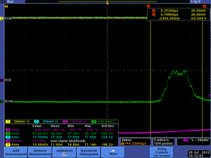
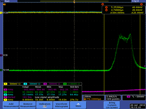
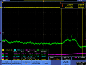
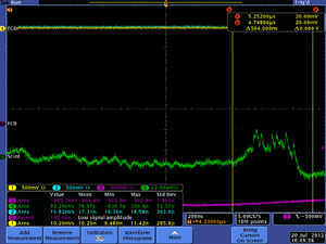
e-/e+ ratio
Scintilator HV: 1200


