Gaseous Medium Physical Concepts
Related Physical Concepts
The gaseous medium inside a detector's chamber contains different physical processes as the detector in operation. As soon as the desired the particles penetrate the gaseous medium, they directly or indirectly (neutron fission) ionize the gas. If the event happened in the active detection area of the detector, a drift electric field is expected to guide the primary and secondary electrons toward the THGEM preamplifiers that are placed vertically with a separation distance within the maximum limit to not lose the electrons by diffusion. The preamplifiers multiply the electrons and create an avalanche directed toward the read out plate that collects these electrons so it appear as pulse on the oscilloscope. Electron recombination, deattachment and capture take place in every stage in the electron trip before they reach the readout plate, they are frequently observed specially in case of the gas pressure is higher than the atmospheric pressure. The preamplifiers may have a discharge on the surface through their operation that may damage them.
The detector parameters are evaluated by the precise mathematical description to each physical process that occurs in any stage before observing the the electrons' signal, those parameter helps to determine the applications and uses like the efficiency, dead time, gain, spatial resolution and robustness.
Ionization
Ionization is the liberation of an electron from the confines of an atom. The minimum amount of energy required to liberate the electron is referred to as the ionization energy. Energy transferred to the electron in excess of this ionization energy will appear in the form of the ejected electron's kinetic energy. Photons or charged particles like fission fragments interacting with a gas volume can induce ionization. The ionization process depends stochastically on the ionization cross section which is mainly affected by the fission fragment energy, type of the fission fragment (heavy or light), the gas pressure in the chamber, and the atomic properties of the gas. Generally, the amount of energy needed to have an ionization event in a gas is the same on average <ref name="Veenhof"> R. Veenhof, Internal Note/TPC, ALICE-INT-2003-29 version 1.0, 2003</ref>, regardless of the incident particle type or energy as shown in the following table for argon gas.
| Type of particle and its energy | 9 keV x-rays | 10 keV electrons | 40 keV electrons | x-rays Ar-37(K-capture)(5-25 keV) + beta | alpha 7.68 MeV | 340 MeV protons |
| Energy per ion-electron pair (eV) | 27.9 1.5 | 27.3 | 25.4 | 27.0 0.5 | 26.25 | 25.5 |
Ionization by fission fragment is not the only source for a signal, but it is not the only ionization process, there are other physical processes occurs in the medium which are related to the gas mixture properties or the preamplifier material properties like: Photoionization, thermal ionization, deionization by attachment (negative ion formation) , photoelectric emission, electron emission by excited atoms or positive ion,and field emission <ref name="Kuffel"/>.
Choosing 90/10 Ar/CO2 gas mixture was not random. The behavior of the mixture is studied based on simulating the ionization in the gas mixture as it is in a gas chamber that has a wire cathode and an anode to produce a high electric field<ref name="Veenhof"/>. Garfield and Magboltz software packages were used for this purpose, Also Imonte 4.5 program can be for more precise simulation but it was not used for the simulations below <ref name="Veenhof"/>. The results of 90/10 ArCO2 simulation is summarized by the following:
Why 90/10 Ar/CO2 Mixture (Simulation by Garfield) <ref name="Veenhof"/>
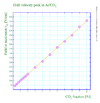
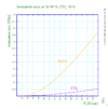
- Drift velocity: Increasing the percentage of CO2 the gas mixture at low electric field increases the drift velocity as shown in the figure:
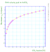
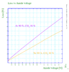
The drift velocity is saturated but at different values depending the percentage of the CO2, so the increase in the drift velocity becomes smaller withe increase in CO2 percentage int he gas mixture as show in the figures below:
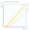
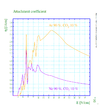
- Gain: It is dependent on Townsend coefficient, the figure below shows the gain-Electric field relationship for different mixtures of ArCO2, in addition to the effect penning of the gain.
The figure above is not accurate enough since Garfield and Magboltz software packages use the first two terms of Legendre polynomials as solution for Boltzmann transport equation (Magboltz may extend to the third term when the simulation goes in the longer time one), but using using IMonte 4.5 uses the spherical harmonics which improved the simulation and make independent of the expansions that describe the electron energy distribution. <ref name="Biagi"> S.Biagi Nucl. Instrum. Methods, vol. A 421, pp. 234–240, 1999</ref >
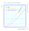
The effect of Penning on Townsend coefficient is represented by the following :
Comparing Ne/CO2 with Ar/CO2 considering the 40 percent of Penning transfer:
- Ionization rate:
- Attachment:
Diffusion
Charged particles diffusion in gas is defined as <ref name="Mason"/> the "disperse" of the particles in a gas "in which there is a net spatial transport" of the charged particles "produced by the gradient in their relative concentrations". Assuming that the charged particles are localized in a gas with a uniform temperature, pressure and has low n charged particle density to ignore Coulomb force.
where D is the diffusion coefficient and J is the number of the charged particle flow per unit time.
Maxwell Boltzmann equation solution describes n as a function of position r and time t, In our case, n represents the number electrons propagating in presence of an electric field. Maxwell Boltzmann equation is "the equation of continuity for the population n f dr dc " where f is velocity distribution function. The equation includes the loss of electrons as they transport across a surface boundary in a volume element dr , and the effect of the electric field (uniform in our case) in accelerating each n dr electrons which changes dc from point to another in the phase space so the number of point loss in a time dt is , in addition to the loss of points n in dc as result of the quasi discontinuous change in position c in velocity space as the electron meets a molecule.
So Maxwell Boltzmann equation can be written as based on the previous assumptions as the following:<ref name="Huxley"> Huxley, L. G. H. Leonard George Holden, The diffusion and drift of electrons in gases, John Wiley and sons, 1974 </ref>
(nf) + (n f c) + (n f + S = 0
The previous equation can be written in terms of the diffusion coefficients and the average velocity of the electrons and it is called the scalar equation of Maxwell Boltzmann equation:
+ (n f_1)+
Assumptions: <ref name="Huxley"/>
- Velocity Shells
The electrons are distributed in the phase space in velocity shell of mean velocity W represented by the following equation
Where W(c) is the resultant velocity of the of the velocities of the electrons in the velocity shell 4, so the population of velocity points in the shell is represented by the n dr . it is assumed for a velocity shell the following distribution function:
is the Legendre polynomial of order k. In the case the mean velocity is independent of the azimuthal angle then its magnitude can be determined by the following:
and the population desity point is :
So the mean velocity is evaluated depending on the former definition is :
It is worth mentioning here that W represent the mean velocity of the electron population and the instantaneous velocity of the of the centroid of n.
- The loss and the gain in the number of points
The loss in the number of points from (c,dc) is depending on and mathematically can be written as . Simultaneously, the gain in the number of points (c,dc) is evaluated using such that is the gain per unit volume (in phase space) per unit time.
So the net change in the number of points in the shell is .
Where and , , N is the molecular density, M is the mass of the molecule, is the momentum transfer cross section for elastic encounters. and is the mean square speed of the molecules.
- Drift velocity and diffusion coefficients
The electron density number, diffusion coefficients and drift velocity relationship is studied for a close chamber contained a travelling swam of electrons in a uniform electric field that directed the swarm toward the +z axis. Mathematically the relationship is assumed as the follwoing:
n - D n ) + W n = 0
where
represents "effective collision frequency for the momentum transfer"<ref name="Huxley"/>, is the is independent on r for a uniform stream that elastic collisions. In this case, is a special form of a general form represented by the following equation:
As a result substituting the main formula in the scalar form of Maxwell Boltzmann , in the absence of the magnetic field ( vanishes) and in a uniform electric field E, we get the following formula:
n - D + ) n - n + W = 0
D is not isotropic as the eE force is applied and is defined as in the equation above, W is represented by the following:
For electrons moving along the z-axis:
n +
D n +
n ) +
- W n = 0
Main differences between electrons and ions behavior in a gas <ref name="Mason">Mason, Edward A. and Earl W. MacDaniel. 1988. Transport Properties of Ions in Gases. John Wiley & Sons. </ref>
Haitham, here is a chance to get help with writing from the help center.
Take the paragraph below to them and learn how to correct it.
H: Sure, but I need to add and edit some more to complete the idea then I will go there.
The ratio between the mass of the electrons and the gas atoms is very small, so with a few eV work done by the electric field, the electrons will gain a high velocity compared to that of the ions when are accelerated under the same electric field.
The probability of low energy electrons to make an interaction is higher than that of the low energy ions, in addition to a supported accurate calculations for the electron drift velocity in the case of electrons. Electrons at low energy have the ability to produce vibrations and excitations in the gas atoms or molecules measured within the lab frame, but the low energy ions have a very low cross sections for the most of the interactions with the gas atoms or molecules, and in case of of having interactions, a complexity is in measuring the products of these interactions. Furthermore, the ratio between a gas atom or molecule mass to the electron mass is very small which simplifies the calculations for the velocity distribution for the electrons in many gases.
Producing electrons is simpler than producing ions in a gas. a number of interactions appear in the gas for producing electrons like thermionic emission, photoemission, or a radioactive decay, on the other hand, creating an ion requires electron bombardment, photo-ionization or an electric discharge which require more sophisticated conditions for the experiment. For instance , the ions are not as sensitive as the electrons for the the non-uniformity of the electric field, electric potential and magnetic field.
The last difference might be a concern in case of the existence of the impurities. The electrons loses most of their energy in the molecular level compared to the electron energy loss within the atomic level for a pure gas. On the other hand, the ionic velocity distribution is not affected by the existence of these impurities except for some cases related to a highly accurate ionic studies in gases.
Gas Quenching
Rewrite the first two sentences so quenching is more clearly described.
Gas quenching is a non-ionizing process occurs when a gas molecules with large cross sections for excitation and vibration states decreases a charged particle energy to create any ionization when the charged particle passes through. Usually, the gas mixture ,contains the ionization event, consists mostly of gas atoms as a main source of electrons and the quenching gas, when the free electrons are scattered after the ionization, their energy is decreased by quenching so the number of secondary electrons becomes less, Consequently, a higher voltage is required to get a gain from this mixture than a medium only has a non-quenching gas<ref name="Sharma"> A.Sharma,F. Sauli, first Townsend coefficients measurements for argon gas european organization for nuclear research (1993) </ref >.
Not only does the quenching process decreases the electron energy, but also decreases the positive ions energy (produced by ionization) when the ions collide with these gas molecules and emits a photon or more from these positive ions. These photons represent the energy loss in a form other than the ionization which is called argon escape peak in case of using Argon gas.
Gas quenching experimentally can be measured by evaluating Townsend first coefficients A,B for different gas mixtures. The following table represents the Townsend first coefficients' values for different ratio of Ar/CO2 gas mixtures<ref name="Sharma"/>:
| Percentage of CO2 | 3.7 | 22.8 | 87.2 | 100 |
| A | 5.04 | 221.1 | 158.3 | 145.1 |
| B | 90.82 | 207.6 | 291.8 | 318.2 |
| 16.2 | 21.6 | 32.9 | 36.4 |
The electric field pressure ratio in the last row is the upper limit of the reduced electric field which Townsend's equation fits considering E as a uniform electric field.
Townsend's Coefficients
Townsend's First Coefficient
Townsend's first Coefficient is defined as "the number of produced by an electron per unit length in the direction of the electric field"<ref name="Kuffel"/>.
- Townsend started his investigations about discharge after fundamental studies were known around 1899 about:
1- Conductivity production by x-rays.
2- Diffusion coefficients, mobility of ions and ion-electron recombinations.
- It was observed for an increment in Electric filed E and pressure P beyond the saturation current value, at some critical value of E and p, the current increases rapidly which will lead to a breakdown of the gap in the form of a spark <ref name="loeb"> L.B.Loeb, basics processes of gaseous electronics, University of California Press, 2nd edition, 1955. </ref>.
- Townsend studied the relationship between E/p as a function of x, where x is the separation distance between the plates. His study was based on the photoelectron emission from the cathode by ultraviolet light at high uniform electric field up to 30kV/cm and 1 atm pressure.
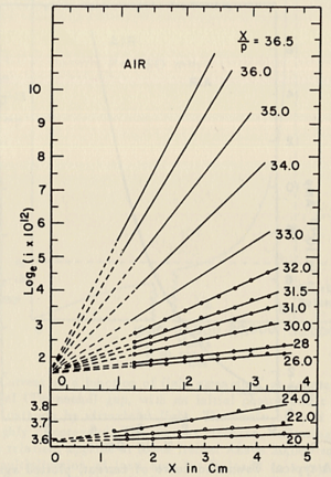
- He plotted different values for E/p, he found that the slope of the line is which is "the number of the new electrons created by single electron in 1 cm path in the filed direction in a gas at appropriately high E/p" <ref name="loeb"/> . Townsend plotted against the distance of separation x, he concluded the following equation
to calculate (the slope) for different values of E/p as shown in the figure:
- Townsend studied as a function of E/p for a given gas, he founded ,for different values of p,
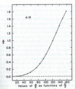
experimentally is different from expected value calculated, but the plots met in values when it represented the relationship between /p as a function of E/p as shwon in the figure below.
- The relationship between /p and E/p is shown below. However, the equation can not predict all the values of /p accurately for different values of E/p, i.e having a single analytical function to fit the experimental results for a gas does not exist, because /p is dependent on the number of electrons produced which changes as the average energy distribution of the ionizing electrons changes <ref name="loeb"/>.
- Theoretical evaluation of as a function of E/p
- The first attempt was done by Townsend when the experimental data were limited by the to the high E/p.
Decreasing the discharge in THGEM
THEGM preamplifier is designed to be rebust, economical, and to get the maximum gain with the least discharge effect.
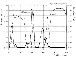
The discharge effect is when you experimentally start observing sparks coming from the detector. Whenever discharge becomes phenomenon to study then the probability of discharge is used. The probability of discharge is defined as the ratio between the observed frequency of the breakdown and source rate <ref name="bachmann"/>.The discharge rate and the source rate can be represented as function of position as shown in the figure.
Producing these sparks refers to many reasons,it is obviously observed when a highly ionizing ion passes through the gaseous chamber and produces enough free electrons to break down the rigidity of surrounding gas by having an avalanche size exceeds Raether limit ( electron-ion pairs) when separating the electrodes vertically with small a distance <ref name="bachmann"> Bachmann et al NIM A 479 (2002) 294-308 </ref > .
Temperature, humidity, and gas flow externally affect the probability of the transition from the proportional multiplication to a discharge at a given potential, the effect clearly appears in absence of the amplification internal effects as the design quality and the history of the electrodes <ref name="bachmann"/>.
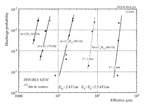
In case of heavily ionizing ions like alpha particles, an increase in gain causes the probability of discharge to increase, but the increment in the probability of discharge can be decreased by choosing an appropriate gap between the THGEM cards <ref name="bachmann"/>. As a result, achieving a maximum gain for an incident particle on a chamber with a specific gas mixture ,under a voltage applied on the THGEM cards, requires an appropriate distance that increases with increment of the ionization rate, i.e an alpha particle requires a bigger gap between the THGEM cards than that of a gamma ray to avoid the discharge effect.(can be experimentally proven).
Reminders
- Basic definitions<ref name="Petrovic"> Z Lj Petrovi´c, S Dujko J. Phys. D
- Appl. Phys. 42 (2009) 194002 </ref>
1- Enhanced electron conductivity: effect shows an increase in the electron drift velocity in a system encounters inelastic collisions with small probability for drift velocity in all directions when it is directed by an electric field.
2- Negative differential conductivity: An effect is observed when the increase in electric field density ratio leads to a decrease in the drift velocity. "NDC was found to be favoured by increasing momentum transfer and decreasing inelastic cross sections and the balance of different processes affecting it can be put into a condition which is relatively accurate". it observed in argon mixtures.
- Physical parameter and its eefect on the detector properties
| physical parameter | Effect on the detector properties <ref name="Veenhof"/> |
| Electron drift velocity | Dead time |
| Electron transverse diffusion | Spatial resolution (momentum resolution), transverse resolution should match the response function (signal width) |
| Townsend Coefficient | Gain which improves the resolution |
| Attachment Coefficient | Losing the information about an ionization, affects the position information and dE/dx identification |
| Gas breakdown | Discharge at that voltage |
| Ion mobility | Determine the rate of collecting the electrons (if the space charge is eliminated), the signal duration in the readout plate |
| Ionization rate | Affect the spatial resolution, dE/dx identification |
Boundary Element Method (BEM)
Boundary Element Method is used to solve Laplace or Poisson Equation, a function u(x,y,z) is solved on the domain boundary and the function partial derivatives are evaluated by integrating on the number of elements on the boundary.<ref name="Kuffel"> Kuffel, W. S. Zaengl, J. Kuffel, High voltage engineering: fundamentals, Biddle Ltd, 2nd edition, 2000 </ref>.
<references/>

