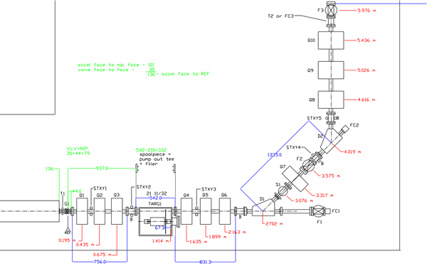
Beamline Drawing 2011 J.Ellis
Jump to navigation
Jump to search
Below is the Beamline sketch
File:HRRL BeamLine 03302011.pdf
| Label | Beam Line Element | Z location from Gate Valve center of element | Dimensions of Element |
| G1 | Fast Gate Valve | 0.000 m | |
| T1 | Torroid 1 | ||
| STXY1 | X-Y steerers 1 | ||
| Q1 | First Quad | 0.175 m | |
| Q2 | Second Quad | 0.425 m | |
| Q3 | Third Quad | 0.675 m | |
| STXY2 | X-Y steerers 2 | ||
| Targ1 | positron production target | 1.175 m | |
| Q4 | Fourth Quad | 1.400 m | |
| Q5 | Fifth Quad | 1.650 m | |
| Q6 | Sixth Quad | 1.8 | |
| STXY3 | X-Y steerers 3 | ||
| F1 | OTR Flag | ||
| FC1 | Faraday Cup 1 | ||
| D1 | First Kiwi Dipole | 2.525 m | |
| S1 | Energy Slits | 2.851 m | |
| STXY4 | X-Y steerers 4 | ||
| Q7 | Seventh Quad | 3.026 m | |
| F1 | Yag SCREEN | 3.296 m | |
| D2 | Second Kiwi Dipole | 3.617 m | |
| Q8 | Eigth Quad | 4.063 m | |
| STXY5 | X-Y steerers 5 | ||
| Q9 | Quad | 4.603 m | |
| Q10 | Quad | 5.143 m | |
| T2 | Torroid 2 | ||
| F3 | Third Flag | 5.712 m | |
| Targ2 | Brehm target ladder | 6.112 m | |
| HOLE@WALL | 6.412 m |
