Kalyan 30 May 08
Case 1
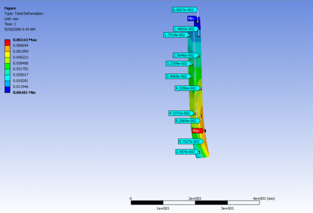
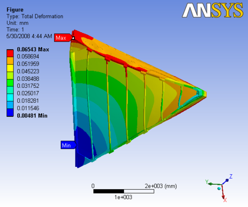
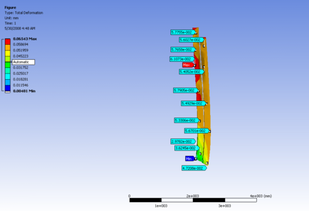
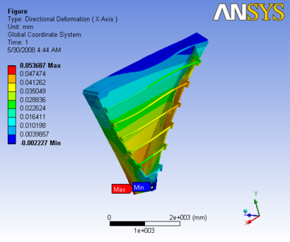
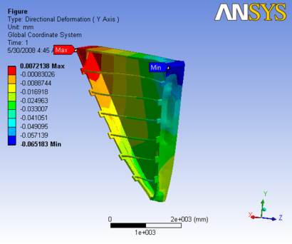
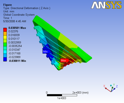
The constraints are as follows The Triangular sections are only constrained on the downstream side and the nose plate is constrained on the upstream side
The report generated by ANSYS is available: File:Case1 slice1.pdf
 |
 |
|
 |
 |
|
Figure 1: Images of Deflection for Sector 1 with case 1 constraints in D,X,Y,Z Directions respectively
Case 2
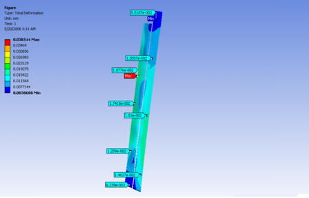
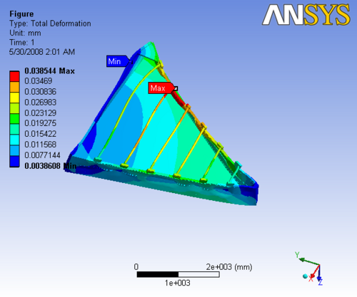
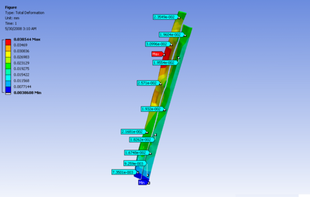
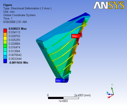
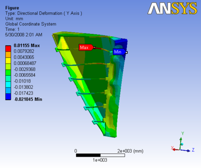
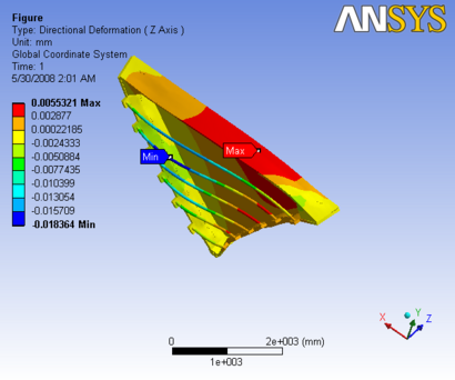
The constraints are as follows The Triangular sections are only constrained on the downstream side and the nose plate is constrained on both sides
The report generated by ANSYS is available: File:Case2 slice1.pdf
 |
 |
|
 |
 |
|
Figure 2: Images of Deflection for Sector 1 with case 2 constraints in D,X,Y,Z Directions respectively
Case 3
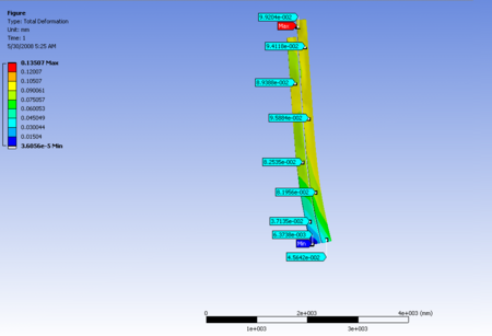
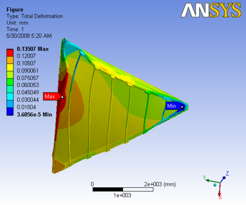
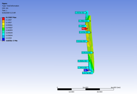
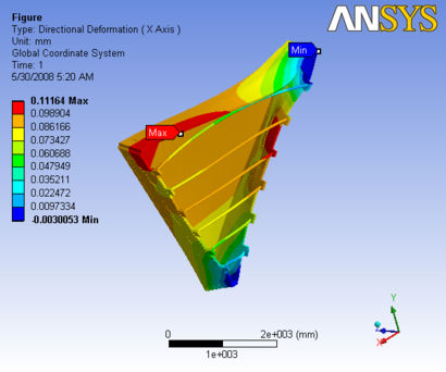
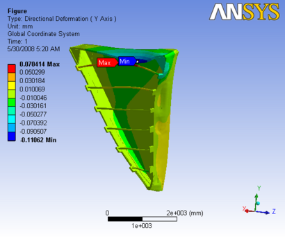
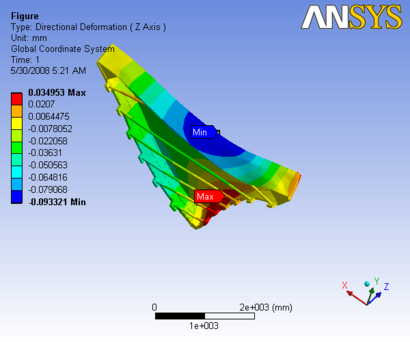
The constraints are as follows The Triangular sections are only constrained on the upstream side and the nose plate is constrained on the upstream side
The report generated by ANSYS is available: File:Case3 slice1.pdf
 |
 |
|
 |
 |
|
Figure 1: Images of Deflection for Sector 1 with case 3 constraints in D,X,Y,Z Directions respectively
Case 4
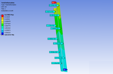
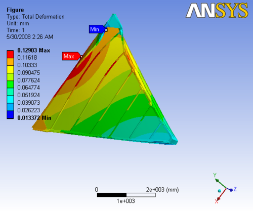
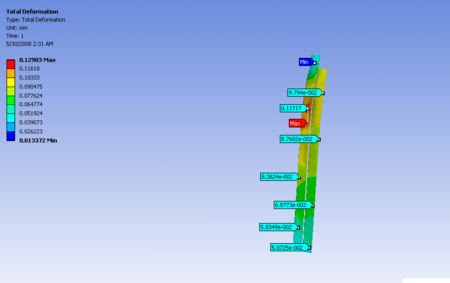
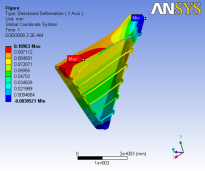
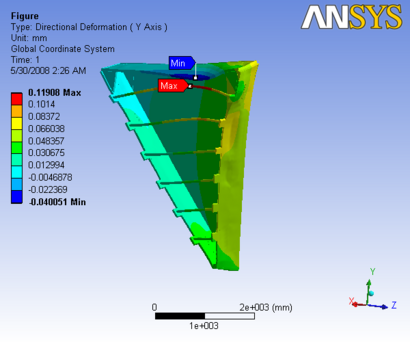
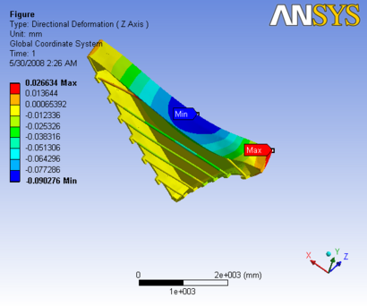
The constraints are as follows The Triangular sections are only constrained on the upstream side and the nose plate is constrained on both sides
The report generated by ANSYS is available: File:Case4 slice1.pdf
 |
 |
|
 |
 |
|
Figure 1: Images of Deflection for Sector 1 with case 4 constraints in D,X,Y,Z Directions respectively
Case 5
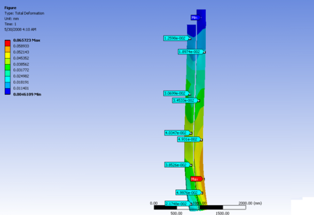
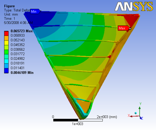
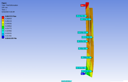
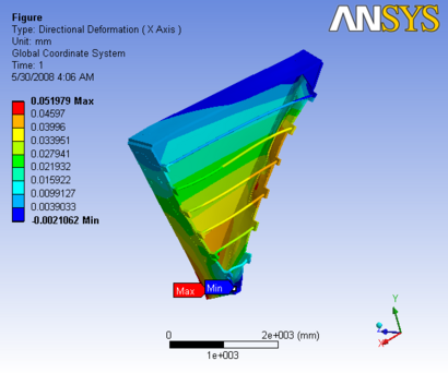
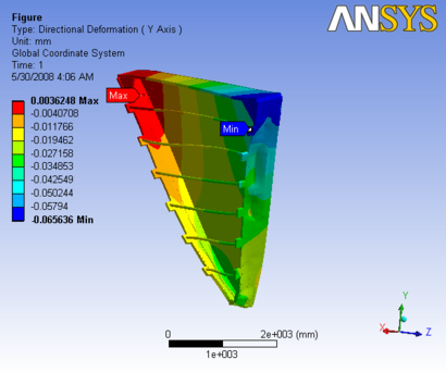
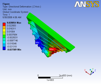
The constraints are as follows The Triangular sections are only constrained on both sides and the nose plate is constrained on the upstream side
The report generated by ANSYS is available: File:Case5 slice1.pdf
 |
 |
|
 |
 |
|
Figure 5: Images of Deflection for Sector 1 with case 5 constraints in D,X,Y,Z Directions respectively
Case 6
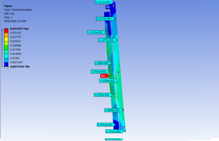
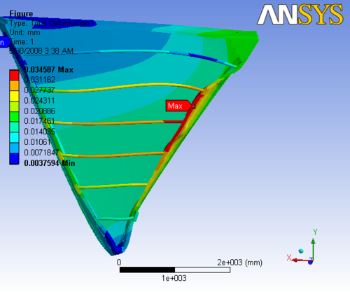
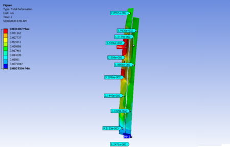
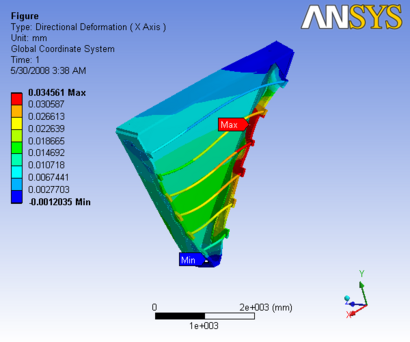
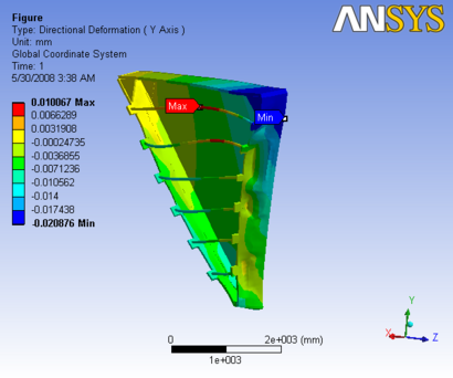
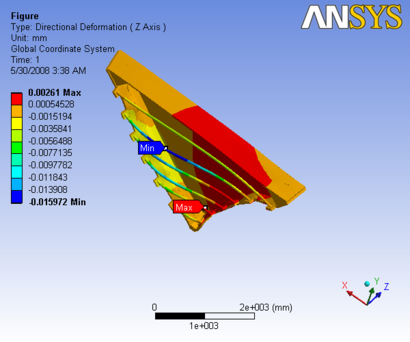
The constraints are as follows The Triangular sections and the nose plate are constrained on both sides
The report generated by ANSYS is available: File:Case6 slice1.pdf
 |
 |
|
 |
 |
|
Figure 6: Images of Deflection for Sector 1 with case 6 constraints in D,X,Y,Z Directions respectively