Kicker Magnets
Kicker Magnet Calculations
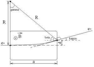
Field needed to bend 44 MeV electrons 0.47 degrees
, ,
- general expression for B-field.
If then and our B-field becomes:
for the coils under consideration. Hence, the B-field needed is:
Magnetic Field Produced by Coils
Assuming the coils we are using are in a solenoidal shape, we have:
which gives us
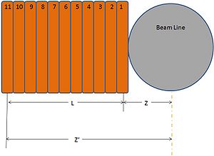
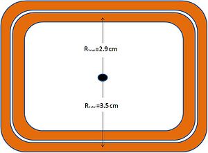
These coils consist of 11 turns of which each turn is two deep. Furthermore, we have an inner and an outer radius . The above magnetic field can be found for both the inner and the outer layer of the coil for each turn of the coil. The maximum current these coils can handle (according to IAC personnel) is 100 Amps. Listed below is the data calculated for 100 Amps.
| Turn Number | Distance from Beam | B-Field (inner) | B-Field (outer) |
| 1 | 2.5 cm | 0.00094392 T | 0.00097 T |
| 2 | 3.15 cm | 0.000675 T | 0.000739 T |
| 3 | 3.8 cm | 0.00048507 T | 0.00056 T |
| 4 | 4.45 cm | 0.00035357 T | 0.000425 T |
| 5 | 5.1 cm | 0.00026237 T | 0.000326 T |
| 6 | 5.75 cm | 0.00019838 T | 0.000253 T |
| 7 | 6.4 cm | 0.00015274 T | 0.000199 T |
| 8 | 7.05 cm | 0.0001196 T | 0.000158 T |
| 9 | 7.7 cm | 0.0000951 T | 0.000128 T |
| 10 | 8.35 cm | 0.0000767 T | 0.000104 T |
| 11 | 9 cm | 0.0000627 T | 0.0000857 T |
Adding the inner and outer fields gives a combined field of 0.007373 T per coil. If we used two coils, one on each side of the beam line we would have a field of 0.014745 T, which is above the needed field to bend electron 0.47 degrees. But, by knowing the field we need, 0.0096 T, we can reverse calculate the current needed to produce 0.0096 T by these coils.
It is found that if we supplied 65 Amps to a pair of these coils we would get a magnetic field in the beam line of 0.0096 T, which is the field required to bend an electron 0.47 degrees.


