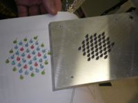
Mini-prototype
Drift Chamber prototypes were constructed to evaluate drift chamber designs for CLAS12

Mini-prototype Performance Measurements
Description of General Operation
Chamber Ionization Gas
Our initial plan will be to use (75/25) flowing though the chamber at a flow rate high enough to exchange the volume once a day.
high Voltage supply
A CAEN 4 channel high voltage supply (N470) will be used to supply HV to the drift chambers. The supply is capable of monitoring currents at the microAmp(A) level and voltages at the Volt (V) level.
Signal Processing

The output signals from the drift chamber will be processed through several
NIM based modules.
Dan or Phil: Insert specs of amplifier needed to see DC signals
A descriminator from Lecroy whith a threshold range from 30 mV up to 1.5 Volts will be used to create a stop pulse for TDCs that are started by scintillators which detect either an electron, during tests at the IAC, or cosmic rays, during tests at the LDS (see below). Hall B has loaded the ISU group a TDC module for the drift chamber studies. Pulse height studies may also be done using an ADC. The DAQ system to manage the signal processing electronics is described below.
DAQ System
The DAQ system is described here
Cosmic tests
Apparatus
Place chamber between two plastic scintillator paddles to check signals. We will use the large area 7 cm by 50 cm paddles with the Russian PMTs operating at 1300 V and threshold > 150 mV to select on energetic cosmic rays. We will arrange the paddles so that the are perpendicular to one another so that looking from above it will have 7 cm by 7 cm overlap. This will allow for testing the chamber along its length
scope pulses
Tony, what do you mean by scope pulses??
Planned tests
We will use the scintillator paddles with cosmic rays.
Tests:
1. Efficiency along length of chamber with overlapping array of scint. paddles optimized for normal incidence. 2. Efficiency as a function of discriminator threshold, i.e. what is the required energy of the cosmic ray. 3. Efficiency as a function of angle. Count rates will decrease so we will have to determine the best overlapping configuration of the paddles.
Electron test facility
IAC 25 MeV electron accelerator
The Idaho Accelerator Center (IAC) operates a 25 MeV Linac capable of delivering instantaneous electron currents of 80 mA/pulse. Pulse widths range from 80 ns to 2 s and repetition rates from single shot to 1 kHz. Drift Chamber testing will use this accelerator to create a secondary electron beam as described below.
secondary electron beam setup
We will need to bring the electron beam to the experimental testing cell. [Picture of IAC here].
We will need to butt an evacuated pipe from the business end of the LINAC to the collimator entrance at the wall. The pipe will have aluminum windows at either end to allow for passage of the electron beam. Phil will be responsible for the design and safety concerns of implementing the pipe. The wall is 8' thick, which is 6' of packed earth sandwiched between 1' of concrete on either side. Upon reaching the wall the electron beam will travel through the hole defined by the collimator aperture. The electron beam will have to travel through a distance of 8' of air as it goes into the experimental test cell. The radiation length of air at STP is over 300 m, so this ought not be a problem. We can place an insert into the collimator on the test cell side to define the electron beam if need be.
We will use Dan's idea of elastic scattering. See: http://www.physics.isu.edu/~cole/IAC/DC_prototype/Detector-Test.pdf
The idea: the beam is incident upon a pencil lead target and the electrons will elastically scatter off the carbon atoms. The prototype will be positioned perpendicular to the incident electron beam so that only the elastically scattered electrons will pass through the chamber. We will place 5 mm by 5 mm scintillators on either side of the chamber. This scintillator arrangement allows for triggering and defining the beam. The paddles will be fixed and the prototype will be on a moveable platform that will be controlled by a stepper motor. This will allow us to measure the sense wire efficiency along the length of the wire and, in particular, the efficiency in close proximity to the feedthroughs.
Description of how beam size will be measured or why it isn't needed.
stepper device
Drift Chamber efficiency measurements
Efficiency -vs- Distance
The secondary electron beam will be moved towards the drift chamber endplate while the efficiency is measured. The results of our tests will be placed below.
Plastic feedthrough
| Distance (mm) | Efficiency |
| 2 | |
| 4 | |
| 6 | |
| 8 | |
| 10 | |
| 12 | |
| 14 |