Forward Time of Flight Detector
FTOF
| SubBank Number
|
Variable
|
Description
|
| 1
|
Sector
|
|
| 2
|
Panel
|
|
| 3
|
ADCL
|
|
| 4
|
ADCR
|
|
| 5
|
TDCL
|
|
| 6
|
TDCR
|
|
| 7
|
ADCLu
|
|
| 8
|
ADCRu
|
|
| 9
|
TDCLu
|
|
| 10
|
TDCRu
|
|
| 99
|
hitn
|
|
Geometry Description (CLAS12 NOTE 2016-?)
Detector Simulation Notes NOTE 2016-?)
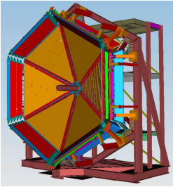 Figure 1: View of the FTOF counters for CLAS12 highlighting the location of the panel-1 and panel-2 counters. The panel-1b counter arrays are shown in orange and the panel-2 counter arrays, mounted around the perimeter of the Forward Carriage, are shown in red. The panel-1a counter arrays mounted just downstream of the panel-1b arrays are not visible in this picture. The Forward Carriage is roughly 10 m in diameter. |
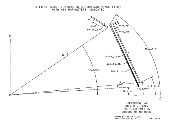 Figure 2: View of the FTOF scintillators for panel-1a, panel-1b, and panel-2 in the sector mid-plane with the key parameters indicated. |
Sectors
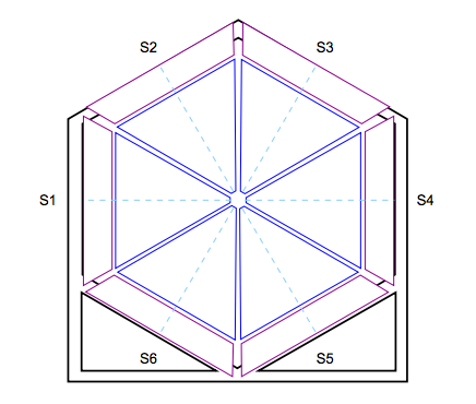
Figure 3: View of the upstream face of the Forward Carriage in Hall B showing the CLAS12 sector naming conversion for Sector 1 (S1) through Sector 6 (S6). The dashed lines denote the mid-planes for each sector.
Panel 1A
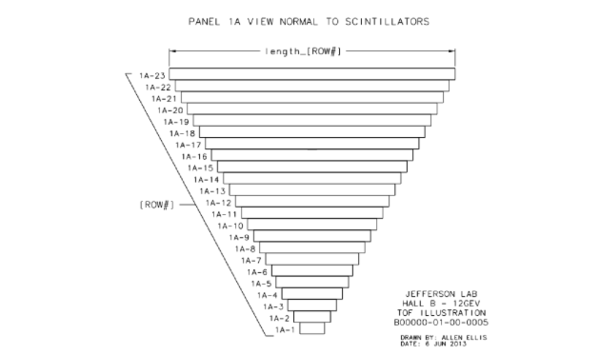
Figure 4: View of the face of a generic FTOF panel-1a array showing the numbering scheme for the 23 scintillators that make up the counters in each of the six sectors of CLAS12.
Panel 1B
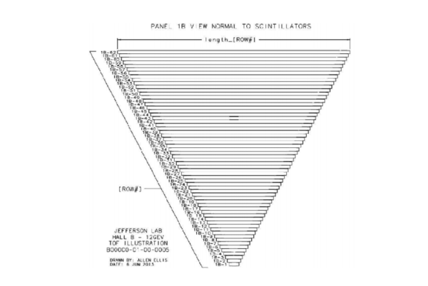
Figure 5: View of the face of a generic FTOF panel-1b array showing the numbering scheme for the 62 scintillators that make up the counters in each of the six sectors of CLAS12.
Analog to Digital Conversion
Time to Digital Conversion


