Difference between revisions of "TDC calibration"
| Line 1: | Line 1: | ||
| − | '''run# 8742''': delay dt=59 ns between the rise side of the common start pulse and the | + | '''run# 8742''': delay dt=59 ns between the rise side of the common start pulse and the fall side of the fake stop signal. |
[[File:dt_100ns_8742_pic.jpg | 500 px]] | [[File:dt_100ns_8742_pic.jpg | 500 px]] | ||
| Line 10: | Line 10: | ||
| − | '''run# 8736''': delay dt=100 ns between the | + | '''run# 8736''': delay dt=100 ns between the rise side of the common start pulse and the fall side of the fake stop signal. |
[[File:dt_100ns_8736_pic.jpg | 500 px]] | [[File:dt_100ns_8736_pic.jpg | 500 px]] | ||
| Line 20: | Line 20: | ||
| − | '''run# 8737''': delay dt=200 ns between the | + | '''run# 8737''': delay dt=200 ns between the rise side of the common start pulse and the fall side of the fake stop signal. |
| Line 32: | Line 32: | ||
The mean of the peak is at 165.5 channel | The mean of the peak is at 165.5 channel | ||
| − | '''run# 8738''': delay dt=300 ns between the | + | '''run# 8738''': delay dt=300 ns between the rise side of the common start pulse and the fall side of the fake stop signal. |
[[File:r8738_tdc.jpg | 500 px]] | [[File:r8738_tdc.jpg | 500 px]] | ||
| Line 44: | Line 44: | ||
| − | '''run# 8739''': delay dt=400 ns between the | + | '''run# 8739''': delay dt=400 ns between the rise side of the common start pulse and the fall side of the fake stop signal. |
The data look like: | The data look like: | ||
| Line 52: | Line 52: | ||
The mean of the peak is at 511.5 channel | The mean of the peak is at 511.5 channel | ||
| − | '''run# 8740''': delay dt=800 ns between the | + | '''run# 8740''': delay dt=800 ns between the rise side of the common start pulse and the fall side of the fake stop signal. |
The data look like: | The data look like: | ||
| Line 60: | Line 60: | ||
The mean of the "main" peak is at 1197 channel | The mean of the "main" peak is at 1197 channel | ||
| − | '''run# 8741''': delay dt=1000 ns between the | + | '''run# 8741''': delay dt=1000 ns between the rise side of the common start pulse and the fall side of the fake stop signal. |
The data look like: | The data look like: | ||
Revision as of 15:00, 19 March 2015
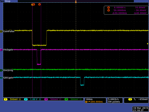
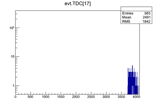
run# 8742: delay dt=59 ns between the rise side of the common start pulse and the fall side of the fake stop signal.
The data look like:
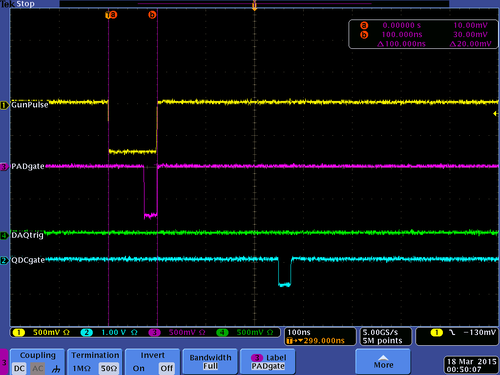
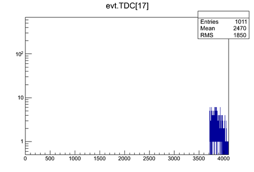
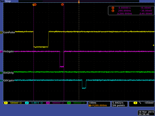
run# 8736: delay dt=100 ns between the rise side of the common start pulse and the fall side of the fake stop signal.
The data look like:
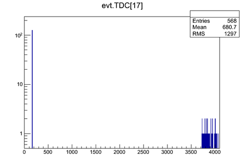
run# 8737: delay dt=200 ns between the rise side of the common start pulse and the fall side of the fake stop signal.
The data look like:
The mean of the peak is at 165.5 channel
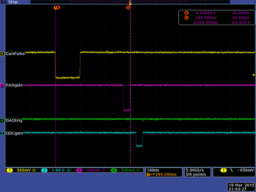
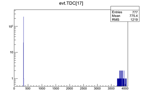
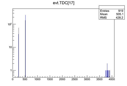
run# 8738: delay dt=300 ns between the rise side of the common start pulse and the fall side of the fake stop signal.
The data look like:
The mean of the peak is at 335.7 channel
run# 8739: delay dt=400 ns between the rise side of the common start pulse and the fall side of the fake stop signal.
The data look like:
The mean of the peak is at 511.5 channel
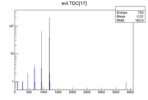
run# 8740: delay dt=800 ns between the rise side of the common start pulse and the fall side of the fake stop signal.
The data look like:
The mean of the "main" peak is at 1197 channel
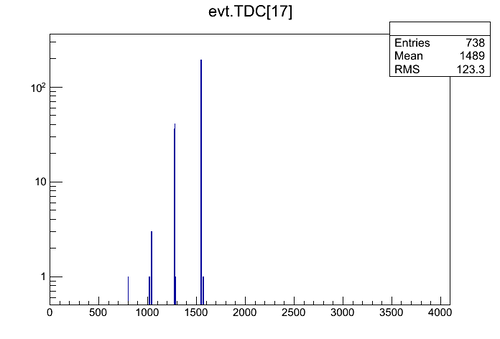
run# 8741: delay dt=1000 ns between the rise side of the common start pulse and the fall side of the fake stop signal.
The data look like:
The mean of the "main" peak is at 1548 channel
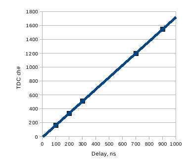
Calibration procedure summary
| Delay, ns | Average TDC ch # |
| 100 | 165.5 |
| 200 | 335.7 |
| 300 | 511.5 |
| 700 | 1197 |
| 900 | 1548 |
TDC calibration plot:
regression line fit y = 1.724728814 x - 7.940677966
The TDC calibration is
