Difference between revisions of "QADC spectrum"
Jump to navigation
Jump to search
| Line 49: | Line 49: | ||
{| border="1" cellpadding="4" | {| border="1" cellpadding="4" | ||
|- | |- | ||
| − | |voltage || channel number || Charge || Average Charge from the figure | + | |voltage (kV) || channel number || Charge (nC) || Average Charge from the figure (nC) |
|- | |- | ||
| − | + | | 2.75 || || || 50 | |
| + | |- | ||
| + | | 2.8 || || || | ||
Revision as of 00:25, 5 November 2013
QDC Analysis
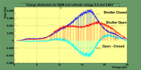
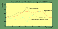
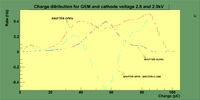
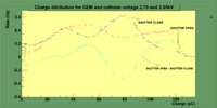
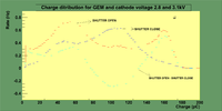
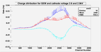
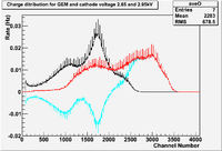
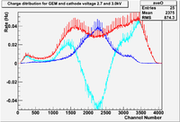
The first test for the detector signal after installing U-233 is by using CAEN V792 Q-ADC (Analog charge to digital converter). The aim of this test is to test the shutter ability to help in distinguishing the emitted particles from U-233 source based on liberated charge from their ionization in gas.
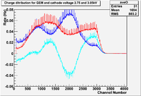
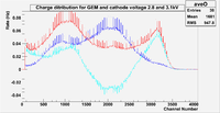
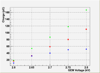
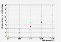
A Non-linear increase in the charge collected by the Q-ADC as the voltage increases for GEM HV-circuit, also the figures show the change in the charge spectrum as the shutter position changed, shutter open's charge spectra show more collected charge than that of shutter close.
|
|
| voltage (kV) | channel number | Charge (nC) | Average Charge from the figure (nC) |
| 2.75 | 50 | ||
| 2.8 |
|
GO BACK [1]
