Difference between revisions of "TF EIM Chapt9"
(→Op-Amp) |
|||
| Line 22: | Line 22: | ||
[[File:TF_EIM_GenOpAmp_EquivCirct.png]] | [[File:TF_EIM_GenOpAmp_EquivCirct.png]] | ||
| + | |||
| + | ==Common Mode== | ||
| + | |||
| + | Common mode input is defined as the situation where the two inputs are equal (<math>V_1 = V_2)</math>. In this case<math> V_1</math> is inverted and will cancel the input <math>V_2</math> so the output becomes Zero in the ideal Op Amp. | ||
Revision as of 02:17, 12 April 2011
Operational Amplifiers (Op Amps)
The operational amplifier is monolithic (single chip) integrated circuit composed of transistors, resistors, diodes, and other components.
The small package produces a device with small capacitance and inductance which is superior to assembling the equivalent circuit with individual components.
Op-Amp
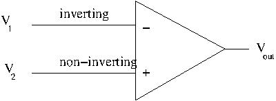
the "-" sign indicates the inverting input terminal and the "+" indicates the non-inverting input.
A positive going input voltage at the non-inverting ("+") input produces a positive going output.
A positive going input voltage at the inverting ("+") input produces a negative going output.
In other words the output is in phase when the input is non-inverting and 180 degrees out of phase when the input is inverting.
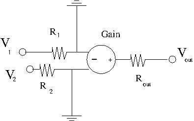
Equivalent circuit
Common Mode
Common mode input is defined as the situation where the two inputs are equal (. In this case is inverted and will cancel the input so the output becomes Zero in the ideal Op Amp.

