Difference between revisions of "Ftof p1a:Integrated Digitized Bank"
(→U) |
|||
| Line 1: | Line 1: | ||
=Forward Time of Flight Detector= | =Forward Time of Flight Detector= | ||
| + | |||
| + | In | ||
| + | each of the six sectors of CLAS12, the FTOF system is comprised of three arrays of counters, | ||
| + | referred to as panels, named panel-1a, panel-1b, and panel-2. Each panel consists of a set | ||
| + | of rectangular scintillators with a PMT on each end. Panel-1 includes the sets of counters | ||
| + | located at forward angles (roughly 5◦ | ||
| + | to 35◦ | ||
| + | ) (where two panels are necessary to meet the | ||
| + | 80 ps average time resolution requirement) and panel-2 includes the sets of counters at larger | ||
| + | angles (roughly 35◦ | ||
| + | to 45◦ | ||
| + | ). The positioning and attachment of the FTOF detector arrays | ||
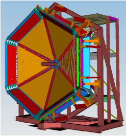
| + | to the Forward Carriage of CLAS12 are shown in Fig. 1. Each of the six panel-1a arrays | ||
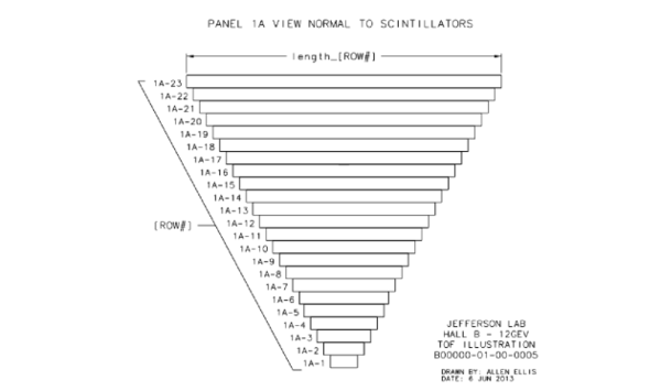
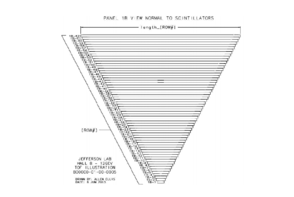
| + | contains 23 counters, each of the new highly segmented panel-1b arrays contains 62 counters. | ||
| + | and each of the panel-2 arrays contains 5 counters. | ||
| + | |||
| + | |||
{| border=1 | {| border=1 | ||
|+ FTOF | |+ FTOF | ||
Revision as of 16:56, 22 July 2016
Forward Time of Flight Detector
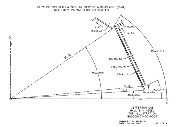
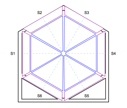
In each of the six sectors of CLAS12, the FTOF system is comprised of three arrays of counters, referred to as panels, named panel-1a, panel-1b, and panel-2. Each panel consists of a set of rectangular scintillators with a PMT on each end. Panel-1 includes the sets of counters located at forward angles (roughly 5◦ to 35◦ ) (where two panels are necessary to meet the 80 ps average time resolution requirement) and panel-2 includes the sets of counters at larger angles (roughly 35◦ to 45◦ ). The positioning and attachment of the FTOF detector arrays to the Forward Carriage of CLAS12 are shown in Fig. 1. Each of the six panel-1a arrays contains 23 counters, each of the new highly segmented panel-1b arrays contains 62 counters. and each of the panel-2 arrays contains 5 counters.
| SubBank Number | Variable | Description |
|---|---|---|
| 1 | Sector | |
| 2 | Panel | |
| 3 | ADCL | |
| 4 | ADCR | |
| 5 | TDCL | |
| 6 | TDCR | |
| 7 | ADCLu | |
| 8 | ADCRu | |
| 9 | TDCLu | |
| 10 | TDCRu | |
| 99 | hitn |
Geometry Description (CLAS12 NOTE 2016-?)
Detector Simulation Notes NOTE 2016-?)
