Difference between revisions of "DU Run"
| Line 5: | Line 5: | ||
[[File:theta_view2.png]] | [[File:theta_view2.png]] | ||
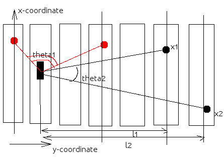
| − | For instance, for the case <math>x1>37.5,x2<37.5</math> the angle is <math>theta2 = acos( \ | + | For instance, for the case <math>x1>37.5,x2<37.5</math> the angle is <math>theta2 = acos( \frac{l1*l2-(x1-37.5)*(37.5-x2)}{\sqrt{l1^2+(x1-37.5)^2}*\sqrt{l2^2+(37.5-x2)^2}} )</math> |
The target was considered to be the point. There was no resolution along y-coordinate of the hit of each detector. All hits were assumed to hit the y-center of each detector. | The target was considered to be the point. There was no resolution along y-coordinate of the hit of each detector. All hits were assumed to hit the y-center of each detector. | ||
Revision as of 22:46, 24 October 2012
Angular dependence of two neutrons emitted from DU target was determined.
The angle was measured as shown below in the picture:
For instance, for the case the angle is
The target was considered to be the point. There was no resolution along y-coordinate of the hit of each detector. All hits were assumed to hit the y-center of each detector.
The angle was measured as shown below in the picture:
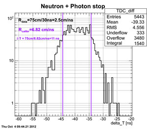
The X-coordinate of the neutron hit of each detector was determined from the TDC difference spectra with application of real calibration factors obtained in separate experiment with Co-60 source. As an example of the cuts applied see the plot below:
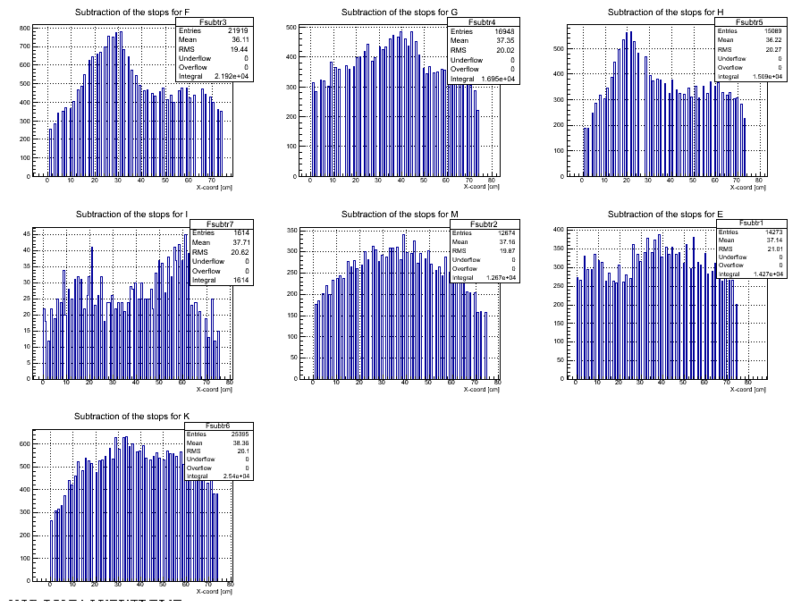
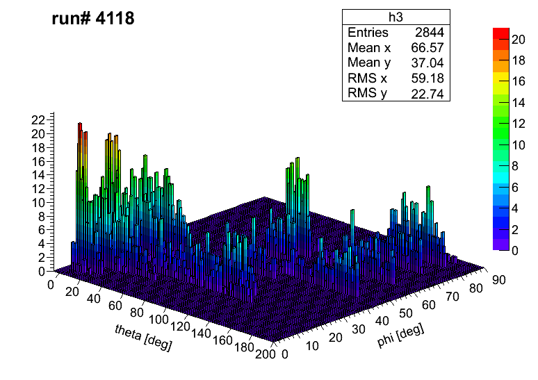
The data from the current run 4118 are plotted below:
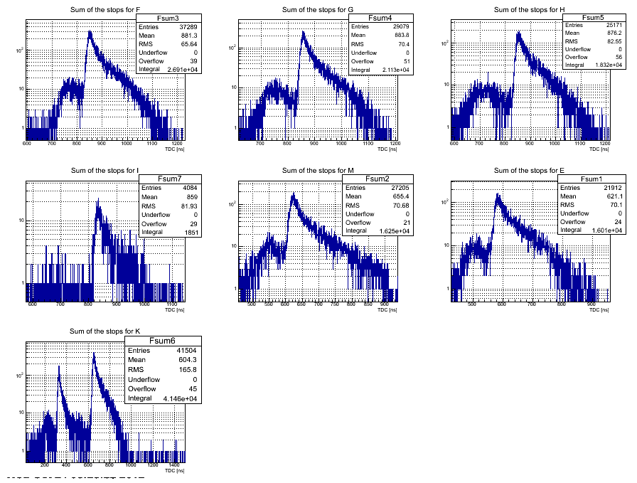
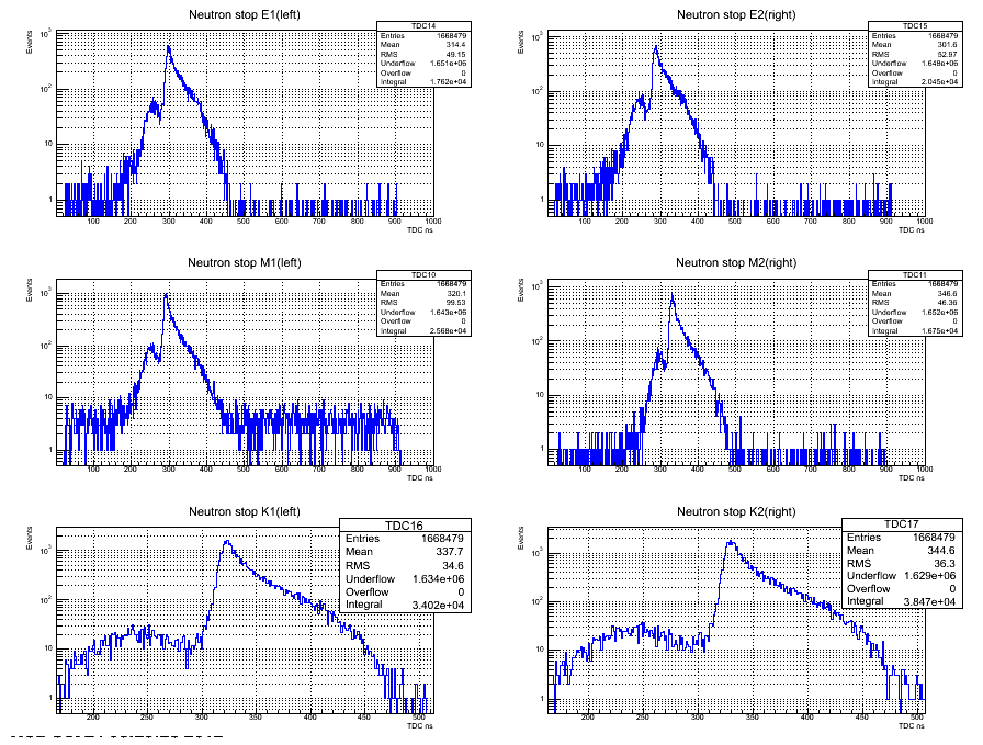
The timing cuts were applied for TDC sum spectra. It should be noticed that time cuts included both neutron and photon areas because in four fold coincidences the photon accidentals will dissappear.
In the case of Det K it was hard to observe the neutron area and the TDC singles spectra were used to set the time cut (see Det K data on the plot below):
After writing a bunch of scripts the root file was created and the data are plotted below:
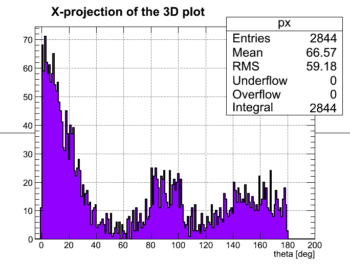
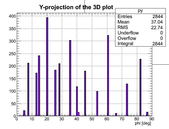
In order to see better and distributions it was created a couple of plots with corresponding projections:
projection of the 3D plot
projection of the 3D plot
The uncertainties on the angle are determined by the width of the neutron detectors and the distance from the target.
The uncertainties on the angle are determined by the width of the TDC difference spectra. Should be discussed.
