Difference between revisions of "Rotating Tungsten Target System"
| Line 141: | Line 141: | ||
| − | <math>I_z~=~\frac{1}{2} \pi \rho h (r_2^4 - r_1^4) = 0.5 \times 3.14 \times 19.25 \times10^3~kg·m ((0.3683~m)^4 - (0.14605~m)^4)</math> | + | <math>I_z~=~\frac{1}{2} \pi \rho h (r_2^4 - r_1^4) = 0.5 \times 3.14 \times 19.25 \times10^3~kg·m^{-1} ((0.3683~m)^4 - (0.14605~m)^4)</math> |
Revision as of 23:05, 28 September 2012
Parts
[More Images ]
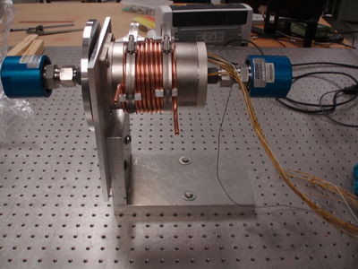
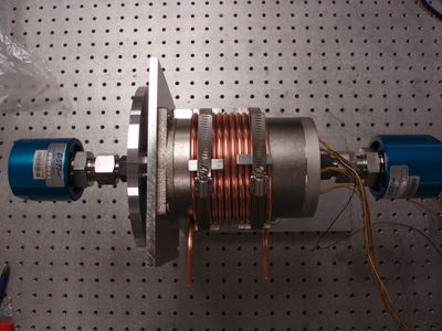
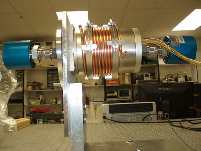
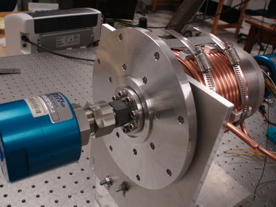
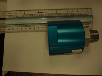
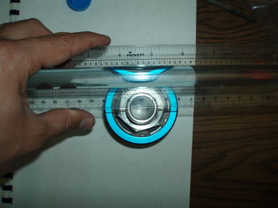
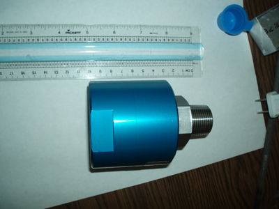
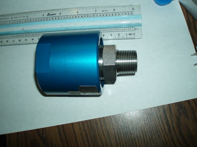
Rotary Union
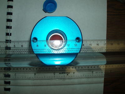
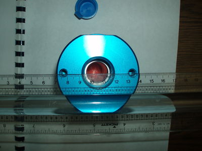
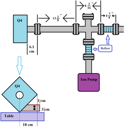
Positron Target Box
The pipe that go through quads has inner diameter: 47.38 * mm
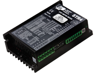
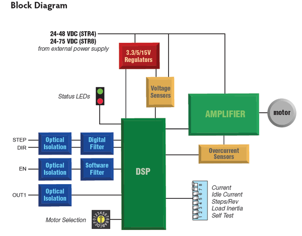
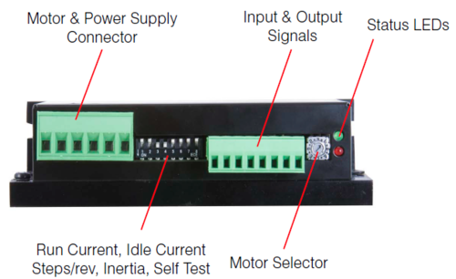
STR8 - Step Motor Drives
Applied Motion Products motor control.
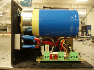
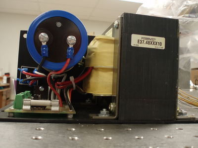
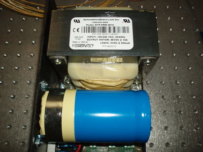
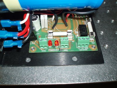
Power Supply
STP-PWR-4810 Power supply for stepping systems, dual output with 48 VDC @ 10A (at full load) unregulated and 5 VDC at 0.5A regulated.
120/240 VAC, 50/60 Hz supply voltage, overcurrent protection.
Document
STR8 Manuals:
Media:STR_Quick_Setup_Guide.pdf
Datasheet:
Media:STR_Brochure_925-0002_RevC.pdf
2D Drawing:
Speed-Torque Curves:
Features
Operates from a 24 to 75 volt DC power supply
Running current up to 7.8 amps per phase
Other Parts needed
1) a 24 to 75 volt DC power supply
2) a source of step signals, such as a PLC or motion controller.
Wire Connection
Wiring the Motor
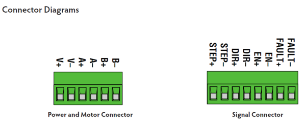
Connect the drive to the motor. Four lead motors can be connected in only one way, as shown in Figure 1. We recommend that eight lead motors be connected in parallel, as shown in Figure 2. If using a non-Applied Motion Products motor, please refer to your motor specs for wiring information.
Step Control
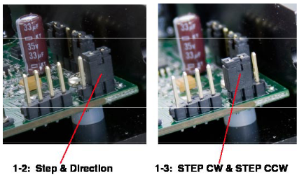
Step Pulse Type Most indexers and motion controllers provide motion commands in the “Step and Direction” format. The Step signal pulses once for each motor step and the direction signal commands direction. However, a few PLCs use a different type of command signal: one signal pulses once for each desired step in the clockwise direction (called STEP CW), while a second signal pulses for counterclockwise motion (STEP CCW). The STR drives can accept this type of signal if you remove the drive cover and move jumper S3 from the “1-2” position to the “1-3” position. In STEP CW/STEP CCW mode, the CW signal should be connected to the STEP input and the CCW signal to the DIR input.
Test
Two Al slabs are place to the disk.
Weight of the Al slab is 235 and 240 grams. Their center of mass are 13 +- 1 cm from the center of disk.
I was able to rotate these two slabs with with maximum frequencies from the pulser
steps/rev    TTL from pulser      Disk rotation
200          1.4  kHz              7 Hz
200 smooth   1.6  kHz              8 Hz
400          3.2  kHz              8 Hz
400 smooth   3.2  kHz              8 Hz
2000         16.5 kHz              8.25 Hz (TTL frequency increase with small increment.)
5000         40   kHz              8 Hz
20000        164  kHz              8.2
If I go above these these speed, motor stops. To reach highest speed, the TTL pulse should be increased with small increment.
W disk inertia calculation
Thickness of the disk is 0.04 inch = 1.016 mm. Disk inner diameter is 5.75 inches (0.14605 m) and outer diameter is 14.5 inches (0.3683 m).
Density of tungsten:
