Difference between revisions of "Beamline design (Y. Kim)"
Jump to navigation
Jump to search
| Line 62: | Line 62: | ||
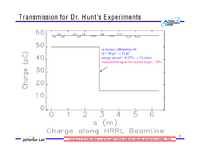
[[File:HRRL_E-transmission_10-14-10.png | 200 px]] | [[File:HRRL_E-transmission_10-14-10.png | 200 px]] | ||
| + | |||
| + | = Expected electron profile after last Kiwi dipole= | ||
| + | |||
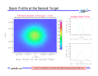
| + | [[File:HRRL_e-Profil_10-14-10.png | 200 px]] | ||
Revision as of 15:17, 14 October 2010
Beam Line Design
Distances
| Element | Distance to Center |
| End of LinacGate Valve | 0.000 m |
| Q1@T1 | 0.175 m |
| Q2@T1 | 0.425 m |
| Q3@T1 | 0.675 m |
| TCOL1 | 1.025 m |
| 1STTG | 1.175 m |
| Q1@T2 | 1.400 m |
| Q2@T2 | 1.650 m |
| Q3@T2 | 1.900 m |
| TCOL2 | 2.250 m |
| KIWI1 | 2.525 m |
| SLIT | 2.851 m |
| Q1@DM | 3.026 m |
| SCREEN | 3.296 m |
| KIWI2 | 3.617 m |
| Q1@T3 | 4.063 m |
| Q2@T3 | 4.603 m |
| Q3@T3 | 5.143 m |
| SCREEN | 5.712 m |
| 2NDTG | 6.112 m |
| HOLE@WALL | 6.412 m |
Beam Optics
Beam Size
