Difference between revisions of "R3"
| Line 94: | Line 94: | ||
##0.004" thick | ##0.004" thick | ||
## impregnated wih graphite fabric | ## impregnated wih graphite fabric | ||
| − | ##Density= | + | ## HRH-10 is the material name |
| + | ## 1/8 represents the cell size (diameter between opposing flat section) | ||
| + | ##Density= 1.8 lb/<math>ft^3</math> | ||
## Young's Modulus= | ## Young's Modulus= | ||
Revision as of 18:25, 11 September 2007
A description of the Region 3 (RIII) Design for CLAS12
Conceptual Design
The location of Region III on this drift chamber can be viewed as
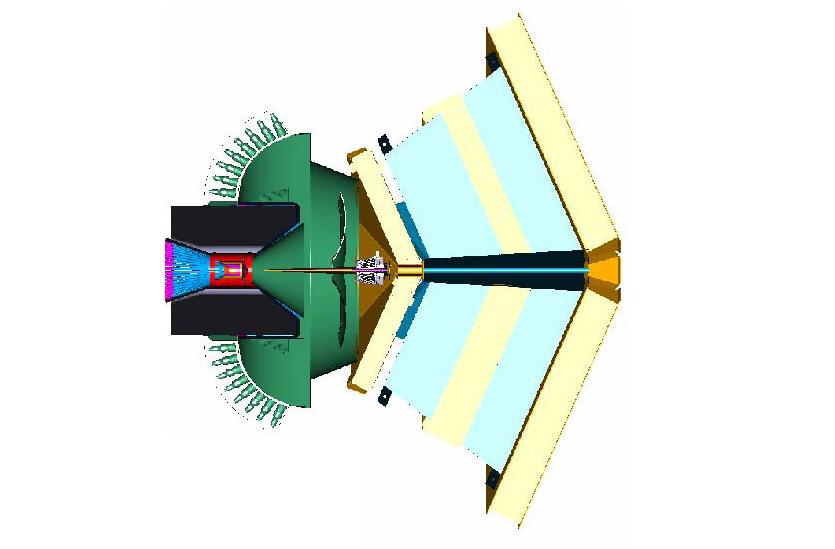
Region III is assembled with 6 Eqi-shaped pieces. Each of these pieces resembles a Pizza slice which together forms the whole chamber.
A view of the 6 piece assembly can be viewed as
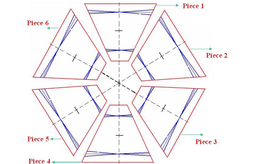
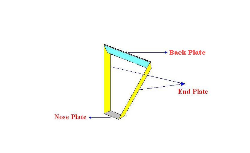
Each of these pieces is made of 3 kinds of plates.
1. Nose Plate (1 No.)
2. End Plate (2 No’s)
3. Face Plate (1 No.)
A Sample assembly of the slice can be Viewed as
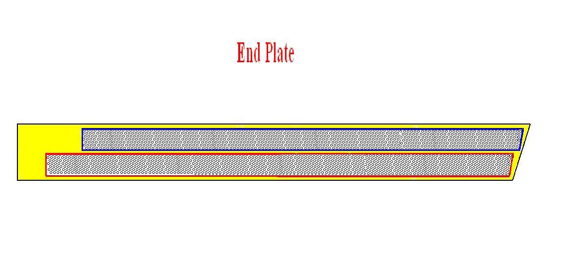
End Plate:
There are 2 end plates for each slice which are attached opposite to each other. There are several holes on each end plate through which sets of sense wires are passed connected both the end plates of a particular slice. The whole area in which holes are drilled on each End plate can be further divided into 2 areas; upward wire area and Downward wire area. A sense wire from upward wire area of end plate ‘A’ is drawn to the downward wire area in the opposite end plate ‘B’ and vice versa. Both these wires are angled at 6 degrees to the imaginary midline, which passes through the Nose plate and the Face Plate of each slice. End plate can be Viewed as
Nose Plate:
This is the place which forms the base for each slice. Both the end plates are attached at the opposite ends of the Nose plate. The angled end of the end plates are attached to this nose plate, so that the end plates are projected at an angle in 3-D.
Face plate:
Face plate is the top plate which holds the end plate together on the top side.
Design criteria
The Design Criteria is to develop all the necessary dimensions from the known dimensions.
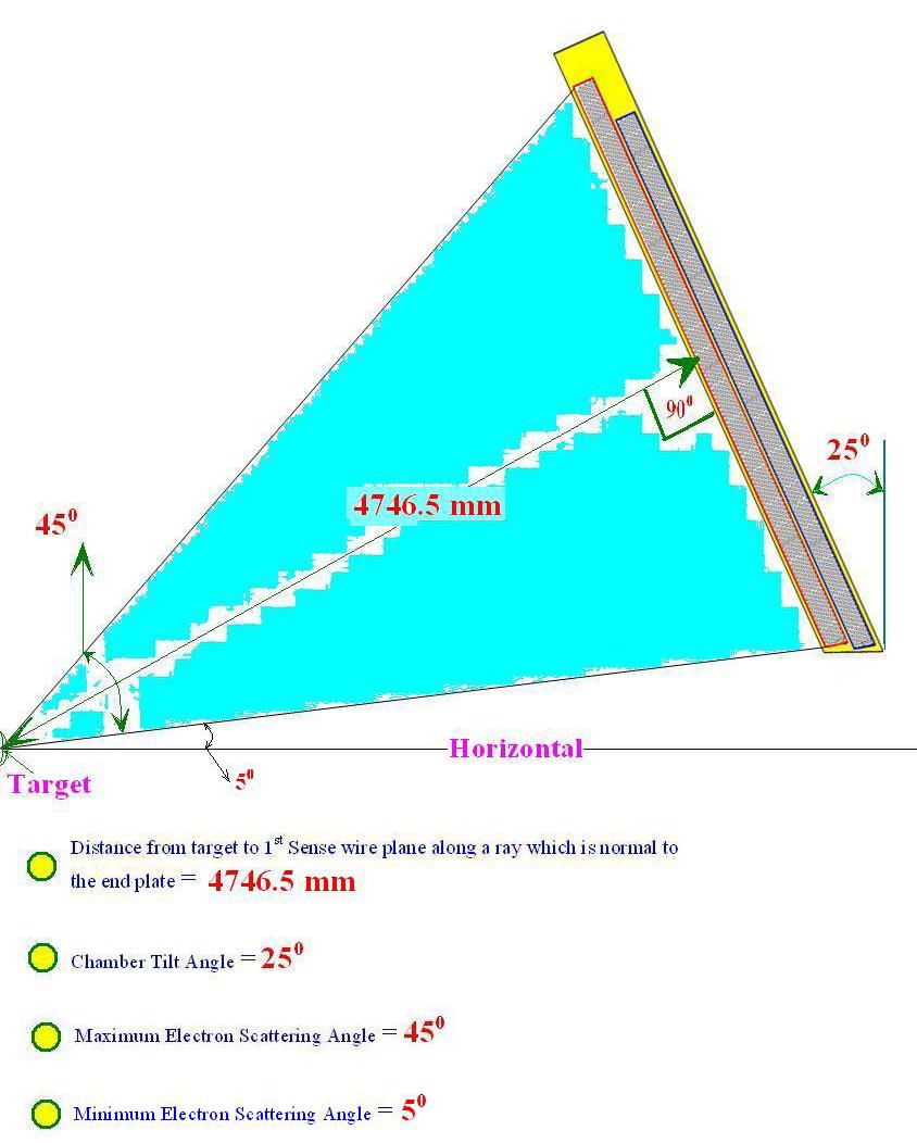
The known dimensions are
• Distance from target to first sense wire plane along a ray which is normal to the end plate = 4746.5 mm
• Chamber Tilt Angle = 25 Degrees
• Maximum Scattering Angle = 45 Degrees
• Minimum Electron Scattering angle = 5 Degrees
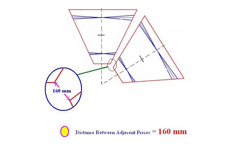
• Distance between the two Adjacent Pieces = 160 mm
The Definition of these given Dimensions can be viewed in the following pictures
Theses known dimensions are used in the determination of the remaining dimensions of the chamber.
Dimensions
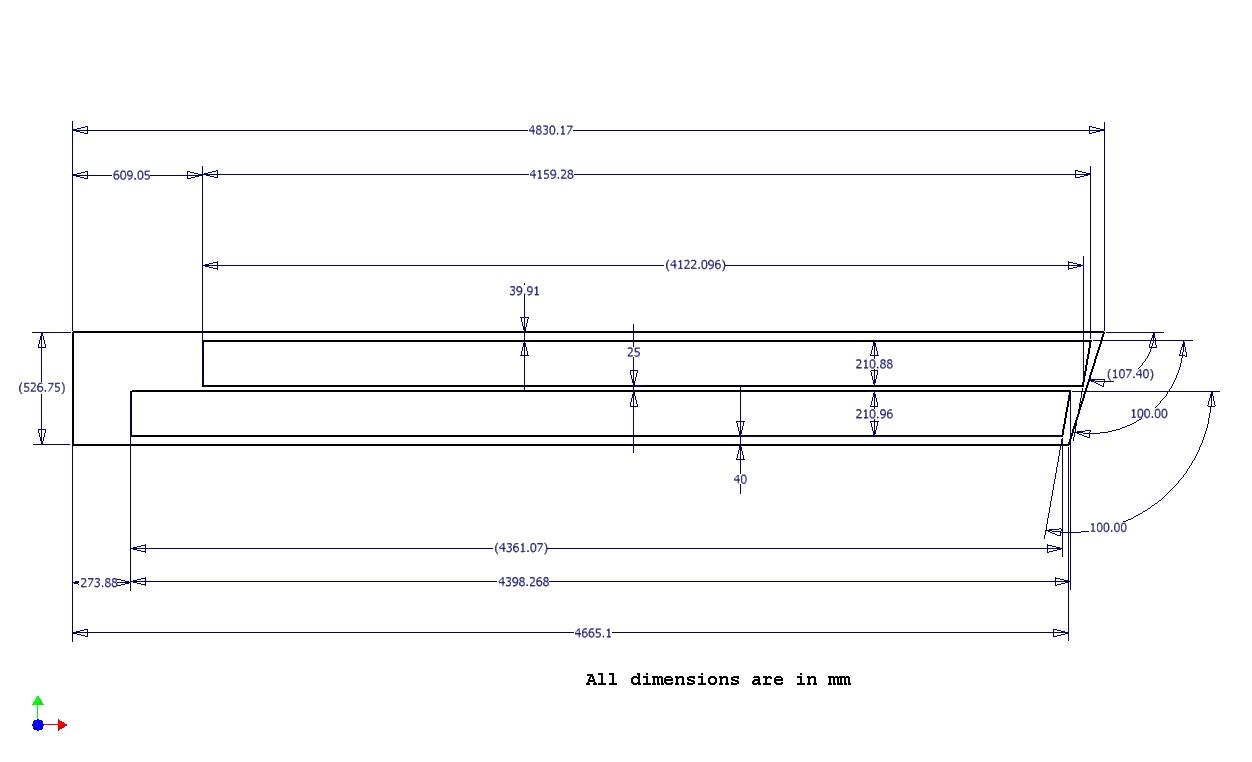
End Plate
Dimensions of the End Plate can be Viewed Below
Face Plate
Nose Plate
Preliminary Design Phase (9/24/07)
Design
Material and cross section of drift chamber frames, endplates, back plates, and nose plates
Endplate material
- Polyeurethane Foam
- R3 Design specification: General Plastics Mfg. Co., "LAST-A-FOAM", FR-3700
- Youngs modulus: 140 MPa
- Density 240 kg/
- Stanless steel plates
- 0.048 inch thick plates on both sides of Foam
- Youngs Modulus=
- Density =
Backplate Material
- Hexcell Honeycomb foam HRH 10-1/8 -1.8
- 0.004" thick
- impregnated wih graphite fabric
- HRH-10 is the material name
- 1/8 represents the cell size (diameter between opposing flat section)
- Density= 1.8 lb/
- Young's Modulus=
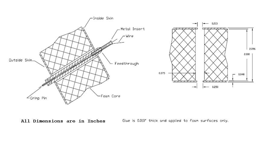
Wire hole patterns and feedthrough details
A Basic View of the Hole on the End Plate with the Feedthrough can be Shown Below
Method for attaching/securing wires
Support bracings, if needed
Lifting attachments and supports
Assembly fixture
Mechanical Analysis
Stress and deflection of endplates under gravity loading
Stress and deflection of endplates under wire loadings
Stress and strain of wires due to gravity and tension loadings
Drawings
Vendors
Provide materials
Perform fabrication
References
- R3 status page at JLAB
- CLAS detector NIM article Media:NIM_A449.pdf
- Mac's CLAS 12 tracking design writeup May 15 , 2005 Media:CLAS12-5-2005.pdf
- Mac's CLAS 12 tracking design writeup Jan. 1, 2007 Media:CLAS12-1-2007.pdf
