Difference between revisions of "CAEN V488 TDC"
Jump to navigation
Jump to search
| (One intermediate revision by the same user not shown) | |||
| Line 1: | Line 1: | ||
| − | |||
[[File:CAEN_V488_TDC_Manual.pdf]] | [[File:CAEN_V488_TDC_Manual.pdf]] | ||
| Line 8: | Line 7: | ||
You can change the dynamic range of the TDC by setting bits using the library function c775setFSR. | You can change the dynamic range of the TDC by setting bits using the library function c775setFSR. | ||
| − | [[Image:CAEN_V488_TDCAddressA.jpg | 400 px]][[Image: | + | [[Image:CAEN_V488_TDCAddressB.jpg | 400 px]][[Image:CAEN_V488_TDCAddressA.jpg | 400 px]] |
| + | [[Image:CAEN_V488_TDCAddressMap.jpg | 400 px]] | ||
{| border="1" |cellpadding="20" cellspacing="0 | {| border="1" |cellpadding="20" cellspacing="0 | ||
| Line 23: | Line 23: | ||
|SW 4 || 0 | |SW 4 || 0 | ||
|} | |} | ||
| + | =ROC library= | ||
| + | |||
| + | ==Compiling library== | ||
| + | |||
= initialize TDC= | = initialize TDC= | ||
| Line 31: | Line 35: | ||
=Common Start/Stop= | =Common Start/Stop= | ||
| + | |||
[[VME_modules]] | [[VME_modules]] | ||
Latest revision as of 23:43, 24 November 2014
The 12 bit ADC conversion time is 5.7 s. A sliding scale technique is used to reduce differential nonlinearity by injecting an offset. This reduces the dynamic range to 0 3840. ADC values between 3841 and 4095 indicate an error.
The TDC measures the time interval between the falling ECL inputs to the start/stop and the channel.
You can change the dynamic range of the TDC by setting bits using the library function c775setFSR.
| Address | |
| Pin | Setting |
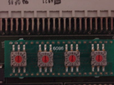
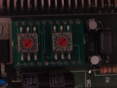
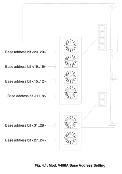
| SW 1 | 2 |
| SW 2 | 2 |
| SW 3 | 0 |
| SW 4 | 0 |
ROC library
Compiling library
initialize TDC
-> c775Init(0x610000)
Initialized TDC ID 0 at address 0x90610000


