Difference between revisions of "TF EIM Chapt1"
| (168 intermediate revisions by 2 users not shown) | |||
| Line 2: | Line 2: | ||
==Charge== | ==Charge== | ||
| − | Every stable and independent object (particle) that has charge has been observed to contain a quantized unit of charge which is a multiple of <math>1.6 \times 10^{-19} Coulombs</math> | + | Every stable and independent object (particle) that has charge has been observed to contain a quantized unit of charge which is a multiple of <math>1.6 \times 10^{-19} \mbox{Coulombs}</math> |
| − | What are the | + | What are the observations/experiments? |
| − | Experiment 1: Matter is composed of Atoms with a positively charged nucleus surround by negatively charged electrons. If we | + | Experiment 1: Matter is composed of Atoms with a positively charged nucleus surround by negatively charged electrons. If we know the charge of one mole of electrons (<math>F</math>= Faradays constant) and the number of electrons in a mole (<math>N_A</math> = Avagadros number)then the charge of a single electron is given by |
:<math>e = \frac{F}{N_A}</math> | :<math>e = \frac{F}{N_A}</math> | ||
| + | |||
| + | The experiment is Electrolysis. | ||
| + | |||
| + | You build up material on a copper cathode that is immersed in an ion solution along with an anode using a battery. | ||
| + | |||
| + | Overtime an ion reaches the cathode a charge passes through the circuit. If we know how much charge passed through the circuit and we measure how much mass accumulated on the cathode we can find Faradays constant. | ||
| + | |||
| + | :<math>F= \frac{Q}{Z} \frac{M}{\Delta m}</math> | ||
| + | |||
| + | M= molar mass (g/mole) | ||
| + | Z = charge of ion used | ||
| + | Q = charge required to accumulate mass <math>\Delta m</math> | ||
| + | |||
| + | <math>F = 9.64846 \times 10^{4}</math>Coul/mole | ||
| + | |||
| + | <math>N_A = 6.02257 \times 10^{23}</math> Particles(Atoms)/mole | ||
Experiment 2: Oil drop experiment | Experiment 2: Oil drop experiment | ||
| − | Experiment 3: The Hall Effect | + | http://www.youtube.com/watch?v=XMfYHag7Liw&feature=player_embedded |
| + | |||
| + | Experiment 3: The Hall Effect | ||
| + | |||
| + | Hall effect: <math>V_H = \frac{I B}{ned}</math> | ||
| + | |||
| + | where | ||
| + | |||
| + | I = current passing through semiconductor | ||
| + | |||
| + | B= Magnetic field applied perpendicular to current direction | ||
| + | |||
| + | d= thickness of semiconductor in direction of applied B-filed | ||
| + | |||
| + | n= density of mobile charge carriers (free electrons or holes) | ||
| + | |||
| + | e= charge of an electron | ||
| + | |||
| + | V_H= Hall voltage which is established by electrons being bent to the walls of the semiconductor | ||
| + | |||
| + | [[File:TF_EIM_HallEffectfig.gif | 200 px]] | ||
| + | |||
| + | |||
;Coulomb: The amount of charge that flows through any cross section of a wire in 1 second if there is a steady current of 1 ampere in the wire. | ;Coulomb: The amount of charge that flows through any cross section of a wire in 1 second if there is a steady current of 1 ampere in the wire. | ||
| Line 61: | Line 99: | ||
| Electric Field || Grass seeds in Insulating Liquid | | Electric Field || Grass seeds in Insulating Liquid | ||
|- | |- | ||
| − | | [[File:ElectricVectorField_NegCharge.png|400 px|thumb|Electric Vector Field for an infinitely long sheet of negative charge]] || [[File:E-Field_grassseedsupendedInsulatingLiq.png|400px|thumb|The orientation of Grass seeds immersed in an insulating liquid with a charged plate. The grass seeds become polarized and align with the electric field]] | + | | [[File:ElectricVectorField_NegCharge.png|400 px|thumb|Electric Vector Field for an infinitely long sheet of negative charge. The vector direction indicates the direction a positive test charge will move]] || [[File:E-Field_grassseedsupendedInsulatingLiq.png|400px|thumb|The orientation of Grass seeds immersed in an insulating liquid with a charged plate. The grass seeds become polarized and align with the electric field]] |
|} | |} | ||
| Line 71: | Line 109: | ||
We now define an Electric field Vector <math>(\vec{E})</math> such that | We now define an Electric field Vector <math>(\vec{E})</math> such that | ||
| − | :<math>\vec{E} = \frac{\vec{F}_q}{q_0} </math> | + | :<math>\vec{E} = \frac{\vec{F}_q}{q_0} </math> ;Notice the direction tells you which way a positive charge will move |
| Line 88: | Line 126: | ||
In other words, the tangent to the direction of the Force vector indicates the direction of the vector field <math>\vec{E}</math>. | In other words, the tangent to the direction of the Force vector indicates the direction of the vector field <math>\vec{E}</math>. | ||
| + | |||
| + | ;Unfortunately, charge can be either positive or negative whereas mass is always a positive quantity so the above uses the convention of a positive (test) charge. | ||
==Electric potential== | ==Electric potential== | ||
| Line 96: | Line 136: | ||
A charge which moves along an electric field line is having work done on it by an electric field. | A charge which moves along an electric field line is having work done on it by an electric field. | ||
| + | === Electric Potential Energy=== | ||
From the work energy theorem, Work is equal to the change in energy of a system | From the work energy theorem, Work is equal to the change in energy of a system | ||
| − | ;<math>W = \Delta</math> Energy | + | ;<math>W = \Delta</math> Kinetic Energy |
The work done moving a change along an electric field line is | The work done moving a change along an electric field line is | ||
| Line 111: | Line 152: | ||
;Note:This is just like the gravitational example of walking up a flight of stairs. | ;Note:This is just like the gravitational example of walking up a flight of stairs. | ||
| − | You will need to apply a force on the positive charge to lift it up because the negatively charge sheet is attracting it (like the earth attracts your mass as you walk up a flight of stairs). For simplicity, let's assume you move at a constant velocity or no acceleration. In other words the attractive coulomb force is balanced by the force you use to push the positive charge to a higher location above the negatively charged infinite sheet. | + | You will need to apply a force on the positive charge to lift it up because the negatively charge sheet is attracting it (like the earth attracts your mass as you walk up a flight of stairs). For simplicity, let's assume you move at a constant velocity or no acceleration. In other words the attractive coulomb force is balanced by the force you use to push the positive charge to a higher location above the negatively charged infinite sheet. (For a more exact calculation you would exert a Force greater then qE to accelerate the charge to a velocity and then exert and equal but opposite force to de-accelerate the charge and bring it to rest; but all this cancels out so lets ignore it) |
<math>W = \int_A^B \vec{F} \cdot d\vec{r} </math> Potential Energy | <math>W = \int_A^B \vec{F} \cdot d\vec{r} </math> Potential Energy | ||
| − | :<math>=\int_A^B q (-\vec{E}) \cdot d\vec{r} | + | :<math>=\int_A^B q (-\vec{E}) \cdot d\vec{r} =-\int_A^B q \vec{E} \cdot d\vec{r} </math> |
<math>(-\vec{E} \cdot d\vec{r}) = \left | \vec{E} \right | dr</math> : The applied force is directed opposite to the Electric field but in the same direction as the displacement<math> \vec{r}</math> | <math>(-\vec{E} \cdot d\vec{r}) = \left | \vec{E} \right | dr</math> : The applied force is directed opposite to the Electric field but in the same direction as the displacement<math> \vec{r}</math> | ||
| + | |||
:<math>=\int_A^B \left | \vec{E} \right | dr = \Delta U = U_B - U_A</math> = Potential Energy Difference | :<math>=\int_A^B \left | \vec{E} \right | dr = \Delta U = U_B - U_A</math> = Potential Energy Difference | ||
| − | The Electric Potential Difference<math> \equiv \Delta V = V_B - V_A = \frac{\Delta | + | |
| + | ;Note:The work done by the electric field is negative (the force from the electric field is opposite to the direction of motion). | ||
| + | |||
| + | Work Energy theorem : <math>W_{tot} = \Delta K.E.</math> | ||
| + | |||
| + | If a conservative force is involved then : <math>W= -\Delta U</math> | ||
| + | |||
| + | <math>W_{tot} = W_{you}+W_{E-field} = \left ( -\int_A^B q \vec{E} \cdot d\vec{r} \right) + \left (-\Delta U_{E-field} \right) = \Delta K.E. = 0</math> | ||
| + | :<math>\Rightarrow \Delta U_{E-field} = W_{you} = -\int_A^B q \vec{E} \cdot d\vec{r}</math> | ||
| + | |||
| + | === Voltage (Electric Potential) === | ||
| + | |||
| + | The Electric Potential Difference<math> \equiv \Delta V = V_B - V_A = \frac{\Delta U_{AB}}{q_0} = \frac{W_{AB}}{q_0}= \int_A^B Edr= -\int_A^B \vec{E} \cdot d\vec{r} > 0</math> | ||
| + | |||
| + | The change in the potential depends on the sign of q_0 | ||
| + | |||
| + | <pre> | ||
| + | Positive (Negative) charge '''naturally''' goes from higher (lower) potential | ||
| + | to lower (higher) voltage. | ||
| + | </pre> | ||
| + | |||
| + | <pre> | ||
| + | Voltage decreases(increases) when positive charge travels parallel(anti-parallel) | ||
| + | to the electric field. | ||
| + | </pre> | ||
When you measure the electric potential (Voltage) you are actually measuring a potential difference<math> \Delta</math> V with respect to some point <math>V_A</math> that is customarily chosen to be zero. | When you measure the electric potential (Voltage) you are actually measuring a potential difference<math> \Delta</math> V with respect to some point <math>V_A</math> that is customarily chosen to be zero. | ||
| Line 132: | Line 198: | ||
If you define the potential <math>V_A</math> to be zero and move the charge a distance <math>d</math> then the voltage is given by | If you define the potential <math>V_A</math> to be zero and move the charge a distance <math>d</math> then the voltage is given by | ||
| − | :V = V_B = Ed | + | :<math>V = V_B = Ed</math> |
| + | |||
| + | ==== Units ==== | ||
| + | |||
| + | ;<math>V = \frac{W}{q_0} \Rightarrow \frac{\mbox{Joule}}{\mbox{Coul}} \equiv \mbox{Volt}</math> | ||
| + | |||
| + | |||
| + | ; <math>[E] = \frac{\mbox{Volts}}{\mbox{m}}</math> | ||
== Electromotive Force(emf)== | == Electromotive Force(emf)== | ||
| Line 138: | Line 211: | ||
An electromotive force is used to describe the external work expended per unit of charge to produce an electric potential difference across two open-circuited terminals. | An electromotive force is used to describe the external work expended per unit of charge to produce an electric potential difference across two open-circuited terminals. | ||
| − | ==Battery== | + | ===Battery=== |
| + | |||
| + | A battery uses a chemical reaction to separate atoms into ions and push electrons onto the negative terminal. The terminal of a battery are usually made out of two different metal electrodes separated by a solution/paste containing ions called the "electrolyte". | ||
| + | |||
| + | Ex: Carbon and zinc electrodes separated by ammonium chloride results in a chemical reaction which generates a 1.5 Volt potential difference between the carbon and zinc electrodes. This is called a cell. From cells you can make batteries by tying cells in series or parallel. | ||
| + | |||
| + | |||
| + | {| border="3" cellpadding="20" cellspacing="0" | ||
| + | |Bat. Type ||Cell emf (V)|| characteristic | ||
| + | |- | ||
| + | | Carbon-Zinc|| 1.5|| flashlight battery, voltage drops slowly with time | ||
| + | |- | ||
| + | |Alkaline-Maganeses|| 1.5 ||long lasting lasting flashlight battery, high current capacity, voltage drops gradually | ||
| + | |- | ||
| + | |Nickel-cadmium|| 1.25 ||rechargeable flashlight battery | ||
| + | |- | ||
| + | |Lead-acid|| 2.6 ||car battery, high currents, rechargeable, sufluric acid electrolyte | ||
| + | |- | ||
| + | |Silver Oxide|| 1.5 ||hearing aids and wathes, low current, constant voltage | ||
| + | |- | ||
| + | |Mercury|| 1.35 ||sudden voltage drops, indoor equipment. | ||
| + | |- | ||
| + | |} | ||
| + | |||
| + | |||
| + | |||
| + | Notice the battery is an isolated voltage source. This means the definition of zero potential can be made at any one point in a circuit with one battery. Because the battery is using a chemical reaction, the electrons come from inside the battery and are not pulled or pushed from the earth (a ground). | ||
| + | |||
| + | As soon as you use the battery the emf changes and is called a voltage because of the internal resistance of the battery (see Lab 1). The voltage rating of the battery represents its "open-circuit" voltage; the voltage when it is not connected. | ||
| + | |||
| + | Unfortunately, batteries have an internal voltage which is only negligible if the external circuits resistance is much larger then the battery's internal resistance. When a battery is "dead" its internal resistance has become equivalent to the circuit the battery is trying to drive (flashlight). The chemical reaction has ceased to effectively pump electrons onto the terminal and as a result "resists" current flow. | ||
| + | |||
| + | ==Current== | ||
| + | |||
| + | === Definition=== | ||
| + | |||
| + | ;<math>I = \frac{d Q}{dt} = \frac{\mbox{Coul}}{\mbox{sec}}</math> | ||
| + | |||
| + | [[File:TF_EIM_DerivationOfCurrent.gif | 400 px]] | ||
| + | |||
| + | Sample calculation of electron drift velocity: | ||
| + | |||
| + | if | ||
| + | : <math>\eta = \frac{\mbox{# e}^1}{\mbox{Volume}}</math> | ||
| + | |||
| + | ::<math>A=</math> area of wire | ||
| + | :: <math>d =</math> length element of wire | ||
| + | |||
| + | then | ||
| + | |||
| + | :<math>Q = (\eta)(e)(Ad) =</math> total charge in wire of length element <math>d</math> | ||
| + | |||
| + | Assume you are running 3 Amps through a 1mm diameter wire of copper. | ||
| + | |||
| + | <math>\rho_{Cu} = 8.94 g/cm^3</math> | ||
| + | |||
| + | A= 63.546 g/mol | ||
| + | |||
| + | <math>\Rightarrow n= \frac{8.94}{63.5} \frac{mol}{cm^3} \times \left (6.02 \times 10^{23} \frac{Atoms}{mole} \right) \times \frac{1 \mbox{free electron}}{atom} = 8.4 \times 10^{28} electrons/m^3</math> | ||
| + | |||
| + | :<math>v_d = \frac{I}{nAq} = \frac{3 Coul/sec}{8.5\times 10^{28} e/m^3 \times \left ( \pi 0.005^2 m^2\right) 1.6 \times 10^{-19} Coul/e} \frac{3600 s}{hr}= 1 m/hr \approx 3.3 ft/hr</math> | ||
| + | |||
| + | ;The electron drift velocity is slow | ||
| + | |||
| + | BUT when I turn on my house light switch the light turns on quickly and not in hours. | ||
| + | |||
| + | Signal speed is <math><</math> c, speed of light (usually < 0.9 c, v_{RG-58U} =0.66 c): Add an electron on one end of the wire and the coulomb force is transmitted at close to the speed of light to the other end of the wire. The speed is less than light due to the interaction of the electrons in the wire medium. | ||
| + | |||
| + | === Convention=== | ||
| + | |||
| + | Current indicates the direction a '''positive charge carrier''' would travel when subject to the given Electric field/Potential difference. | ||
| + | |||
| + | ==Resistance== | ||
| + | |||
| + | ===General Properties=== | ||
| + | |||
| + | A resistor is basically a parallel piped of some material (usually Carbon) which has a conductor on each end. | ||
| + | |||
| + | A common analogy is to think of current flowing through a wire like water flowing through a pipe. | ||
| + | |||
| + | The longer the pipe the harder it is to push water through it. | ||
| + | |||
| + | The bigger the pipe, the easier it is to push water through it. | ||
| + | |||
| + | As a result of this physical observation you have that | ||
| + | |||
| + | :<math>R \propto \frac{L}{A} \equiv \rho \frac{L}{A}</math> | ||
| + | |||
| + | where | ||
| + | |||
| + | :<math>\rho \equiv</math> resistivity = constant of proportionality | ||
| + | |||
| + | Resistivity is a bulk property of matter such that a good conductor has a small value or resistivity (large value of conductivity) whereas bad conductors have large resistivity values. | ||
| + | |||
| + | Ex: Low resistivity= metals, plasmas, salt solutions, humans | ||
| + | |||
| + | High resisitvity= wood, rubber, plastic, glass, quartz | ||
| + | |||
| + | === Convention=== | ||
| + | |||
| + | |||
| + | In circuits, a resistor is denoted using the symbol | ||
| + | |||
| + | [[File:TF_EIM_ResistorSymbol.png|200px]] | ||
| + | |||
| + | Resistor packages are labeled with the color coding below | ||
| + | |||
| + | [[File:TF_EIM_ResistorColorCode.gif|200px]] | ||
| + | {| border="1" |cellpadding="20" cellspacing="0 | ||
| + | |- | ||
| + | | || Color || value | ||
| + | |- | ||
| + | | || black || 0 | ||
| + | |- | ||
| + | | || brown|| 1 | ||
| + | |- | ||
| + | | R || Red || 2 | ||
| + | |- | ||
| + | | O || Orange || 3 | ||
| + | |- | ||
| + | | Y || Yellow || 4 | ||
| + | |- | ||
| + | | G || Green || 5 | ||
| + | |- | ||
| + | | B || Blue || 6 | ||
| + | |- | ||
| + | | V || Violet || 7 | ||
| + | |- | ||
| + | | || gray || 8 | ||
| + | |- | ||
| + | | || white || 9 | ||
| + | |} | ||
| + | |||
| + | |||
| + | Typical resistors have three colors close to each other on one side. | ||
| + | |||
| + | The resistance is given by | ||
| + | |||
| + | :<math>R = (1st digit color)(2nd digit color) \times 10^{third color}</math> | ||
| − | + | If the tolerance is given it will appear as a single color line on the opposite side of the three color lines | |
| + | |||
| + | Tolorance = color of fourth band usually | ||
| + | :Gold = \pm 5% | ||
| + | :Silver = \pm 10% | ||
| + | :No color = \pm 20% | ||
=Ohm's Law= | =Ohm's Law= | ||
;resistance is a constant | ;resistance is a constant | ||
| − | :<math>R = \frac{ | + | :<math>R = \frac{d V}{dI}</math>= constant |
| + | Ohm's law is a statement the the resistant of a material is constant. | ||
| + | |||
| + | ;Ohms law does not hold for all materials, (tunnel diode). | ||
| + | |||
| + | [[File:TF_EIM_OhmLawfails.png|200px]] | ||
| + | |||
| + | ==Resistors in Series== | ||
| + | |||
| + | Resistors in series have the same current passing through them because of current conservation | ||
| + | |||
| + | [[File:TF_EIM_ResistersInParallel.jpg| 200px]] | ||
| + | |||
| + | using Ohm's Law | ||
| + | |||
| + | <math>R_{tot} = \frac{\Delta V}{I} </math> | ||
| + | :<math> = \frac{V_2 -V}{I} </math> | ||
| + | :<math> = \frac{V_2-V_1+V_1 -V}{I} </math> | ||
| + | :<math> = \frac{V_2-V_1}{I} + \frac{V_1 -V}{I} </math> | ||
| + | :<math> = R_2 + R_1 </math> | ||
| + | |||
| + | Resisters in series add | ||
| + | |||
| + | ===Voltage Divider=== | ||
| + | |||
| + | Consider the two resistors in series below | ||
| + | |||
| + | [[File:TF_EIMVoltageDivider.gif|400 px]] | ||
| + | |||
| + | What is the ratio of <math>V_{out}</math> to <math>V_{in}</math> | ||
| + | |||
| + | |||
| + | |||
| + | Ohm's Law <math>\Rightarrow</math> | ||
| + | |||
| + | <math>V_{in} = I(R_1+R_2)</math> | ||
| + | |||
| + | <math>V_{out} = IR_2</math> | ||
| + | |||
| + | so | ||
| + | |||
| + | <math>\frac{V_{out}}{V_{in}} = \frac{R_2}{R_1+R_2}</math> | ||
| + | |||
| + | ==Resistors in parallel== | ||
| + | |||
| + | |||
| + | For resistors in parallel | ||
| + | |||
| + | [[File:TF_EIMResistorInParallel.gif|400 px]] | ||
| + | |||
| + | Ohm's Law says | ||
| + | |||
| + | <math>\Delta V = I_1 R_1 = I_2 R_2</math> | ||
| + | |||
| + | Conservation of current says | ||
| + | |||
| + | :<math>I= I_2+I_2 = \frac{\Delta V}{R_1} + \frac{\Delta V}{R_2} = \left ( \frac{1}{R_1} + \frac{1}{R_2} \right ) \Delta V = \frac{\Delta V}{ R_{\parallel}}</math> | ||
| + | |||
| + | :<math> \frac{1}{R_{\parallel}}=\left ( \frac{1}{R_1} + \frac{1}{R_2} \right )</math> | ||
| + | |||
| + | ==Power== | ||
| + | |||
| + | As shown before | ||
| + | |||
| + | Potential energy = <math>U = q V</math> = charge <math>\times</math> Voltage | ||
| + | |||
| + | Power = <math>\frac{\mbox{Energy}}{\mbox{time}} = \frac{q}{t} V = I V = I (IR) = I^2R =\left (\frac{V}{R} \right ) V = \frac{V^2}{R}</math> | ||
| + | |||
| + | ===Parallel or Series Light bulbs?=== | ||
| + | |||
| + | Light bulbs are basically resistors so hot that they give off light. | ||
| + | |||
| + | If you have 1 battery and a bunch of lights should you wire the light up in parallel or series to have the same amount of light come out of each light bulb? | ||
| + | |||
| + | |||
| + | If in series then the voltage drops in half across each bulb | ||
| + | |||
| + | <math>P = \frac{\left (\frac{V}{2} \right)^2}{R} = \frac{V^2}{4R}</math> | ||
| + | |||
| + | If in parallel then each bull | ||
| + | |||
| + | Current is the same through each resistor and the voltage drop is the same so | ||
| + | |||
| + | <math>P = I^2R = \frac{V^2}{R}</math> | ||
| + | |||
| + | ;Wire those Xmas lights in parallel | ||
| + | |||
| + | ==Ideal/Real battery== | ||
| + | |||
| + | |||
| + | In an ideal battery you close the switch on a circuit, something complicated happens, then you reach a steady state current. An ideal battery will maintain a constant potential but not a constant current. | ||
| + | |||
| + | A real battery has an internal resistance such that a terminal voltage is supplies after there is a voltage drop within the battery due to its internal resistance. A battery "dies" because the internal resistance increases so much that the terminal voltage drops to zero preventing electrons from being pushes around outside the battery. The internal resistance increases when the chemical interactions inside the battery start to decrease. | ||
| + | |||
| + | |||
| + | :<math>V_{\mbox{terminal}} = V_{\mbox{bat}} - V_{\mbox{internal}} = V_{\mbox{bat}} - IR_{\mbox{internal}}</math> | ||
| + | |||
| + | <math>V_{bat}</math> = terminal voltage when there is no current in the external circuit being driven | ||
| + | |||
| + | {| border="1" |cellpadding="20" cellspacing="0 | ||
| + | |- | ||
| + | | Ideal Battery || Real Battery | ||
| + | |- | ||
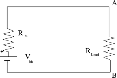
| + | | [[File:TF_EIM_Lab1b.png|400 px|thumb|An Ideal battery with a resistor across it's terminals]] || [[File:TF_EIM_Lab1c.png|400px|thumb|A real battery]] | ||
| + | |} | ||
| + | |||
| + | |||
| + | =Kirchhoff's Laws= | ||
| + | |||
| + | ==Loop Theorem/ Voltage Law/Conservation of Energy== | ||
| + | |||
| + | "Around any closed loop circuit, the algebraic sum of all the voltage drops must equal zero." | ||
| + | |||
| + | ===Real battery example=== | ||
| + | |||
| + | In the real battery example above you have a voltage source with two resistors in parallel. | ||
| + | |||
| + | |||
| + | ====Convention for current direction==== | ||
| + | |||
| + | Positive current flows into the positive side (higher voltage) of a resistor and out the negative side (lower potential) side. | ||
| + | |||
| + | [[File:TF_EIM_Lab1c_CurrentConv.png| 200 px]] | ||
| + | |||
| + | The arrow in the above picture identifies the direction of "positive" current. You should try to follow the direction of positive current when you define a loop to traverse the circuit and apply the loop theorem. | ||
| + | |||
| + | If I begin my loop on the positive terminal of the battery with <math>V_{bb}</math>, then the first voltage drop I encounter as I traverse the circuit clockwise is the battery's internal resistor <math>R_{int}</math>. I then encounter a voltage drop across the load resistor R_{load} before completing my loop around the circuit. | ||
| + | |||
| + | Algebraically the voltage drop may be written as | ||
| + | |||
| + | :<math>V_{bb} - I R_{int} - I R_{load} = 0</math> | ||
| + | : <math>\Rightarrow V_{bb} = I R_{load} + I R_{int}</math> | ||
| + | |||
| + | The largest voltage drop occurs when <math>R_{load} >> R_{int}</math> since at any given time <math>R_{int}</math> is a constant (though it increases with battery life until the battery is no longer able to drive the circuit). | ||
| + | |||
| + | ;Note: The highest current occurs when <math>R_{load}</math> is the smallest. If you plot<math> V_{term} = I R_{load}</math> (the voltage measured across the battery terminal) as a function of <math>I</math> where the current is increased by decreasing the value of <math>R_{load}</math> then you will see a line with a y-intercept equivalent to <math>V_{bb}</math> and a slope equivalent to<math> R_{int}</math>. | ||
| + | |||
| + | : <math> V_{term} = I R_{load} </math> | ||
| + | :: <math> = V_{bb} - I R_{int} </math> | ||
| + | :: <math> = - I R_{int} + V_{bb} </math> | ||
| + | : <math>Y = mX+ b </math> | ||
| + | |||
| + | (see EIM Lab 1 [[Lab_1_TF_EIM]]) | ||
| + | |||
| + | ==Current Law/Conservation of Charge== | ||
| + | |||
| + | "At any junction of wires in a circuit, the sum of all currents entering the junction is exactly equal to the sum of all currents leaving the junction." | ||
| + | |||
| + | ===Voltage Divider example=== | ||
| + | Consider the circuit below | ||
[[File:TF_EIM_Lab1.png | 400 px]] | [[File:TF_EIM_Lab1.png | 400 px]] | ||
| − | |||
| − | The | + | An algebraic equation representing conservation of current at the junction can be written as |
| + | |||
| + | :<math>I_1= I_2 + I_3</math> | ||
| + | |||
| + | |||
| + | Applying conservation of energy (Voltage loop theorem) to the circuit in 2 loops we would write | ||
| + | |||
| + | :<math>V_{bb} = I_1 R_1 + I_2 + R_2</math> | ||
| + | :<math>0=I_3R_3-I_2R_2</math> | ||
| + | |||
| + | |||
| + | The above description results in a system of 3 equations and 7 variables . A solution exists if there are only 3 unknowns or less. | ||
| + | |||
| + | ====Equivalent Circuit==== | ||
| + | |||
| + | In the above voltage divider circuit, one could write an equivalent circuit by simplifying the resistors in series and parallel into one resistor. | ||
| + | |||
| + | :[[File:TF_EIM_Lab1b.png|200 px]] | ||
| + | |||
| + | where | ||
| + | |||
| + | :<math>R_{Load} = R_1 + \frac{1}{\frac{1}{R_2} + \frac{1}{R_3}}</math> | ||
| + | |||
| + | Then | ||
| + | |||
| + | :<math>V_{bb} = I_1 R_{Load}</math> | ||
| + | |||
| − | + | ==== Find currents when Resistances are known==== | |
| − | == | + | Returning to the system of 3 equations and 7 variables we can conclude that the voltage <math>V_{bb}</math> must be known as well as the resistances in order to determine the currents. |
| − | == | + | |
| + | The system of equations may be written | ||
| + | |||
| + | :<math>0 = -I_1 + I_2 + I_3</math> | ||
| + | :<math>V_{bb} = I_1 R_1 + I_2 R_2</math> | ||
| + | :<math>0=-I_2R_2 + I_3R_3</math> | ||
| + | |||
| + | You can solve the above for <math>I_1</math>, <math>I_2</math>, and <math>I_3</math> by algebraic manipulation or Matrix Methods (determinant or inversion/Gauss-Jordan elimination) | ||
| + | |||
| + | |||
| + | ;Matrix Method | ||
| + | |||
| + | :<math>\left( \begin{array}{c} 0 \\ V \\0 \end{array} \right) = \left( \begin{array}{ccc} -1 & 1 & 1\\ R_1 & R_2 & 0 \\0 & -R_2 & R_3 \end{array} \right)\left( \begin{array}{c} I_1 \\ I_2 \\ I_3\end{array} \right)</math> | ||
| + | |||
| + | |||
| + | Solutions exist as long as | ||
| + | |||
| + | :<math>\left| \begin{array}{ccc} -1 & 1 & 1\\ R_1 & R_2 & 0 \\0 & -R_2 & R_3 \end{array} \right| =-R_2R_3-R_1R_2-R_1R_3\ne 0</math> | ||
| + | |||
| + | ;Method of Determinants <math>\Rightarrow</math> | ||
| + | |||
| + | |||
| + | : <math>I_1 = \frac{\left| \begin{array}{ccc} 0 &1 & 1\\V & R_2 & 0 \\ 0 & -R_2 & R_3 \end{array} \right| }{\left| \begin{array}{ccc} -1 & 1 & 1\\ R_1 & R_2 & 0 \\0 & -R_2 & R_3 \end{array} \right| }</math>: <math>I_2 = \frac{\left| \begin{array}{ccc} -1 &0 & 1\\R_1 & V & 0 \\ 0 & 0 & R_3 \end{array} \right| }{\left| \begin{array}{ccc} -1 & 1 & 1\\ R_1 & R_2 & 0 \\0 & -R_2 & R_3 \end{array} \right| }</math>: <math>I_1 = \frac{\left| \begin{array}{ccc} -1 &1 & 0\\0 & R_2 & V \\ 0 & R_2 & 0 \end{array} \right| }{\left| \begin{array}{ccc} -1 & 1 & 1\\ R_1 & R_2 & 0 \\0 & -R_2 & R_3 \end{array} \right| }</math> | ||
| + | |||
| + | |||
| + | ;Matrix Inversion/Gauss-Jordan elimination | ||
| + | |||
| + | If <math>\vec V</math> and <math>\vec I</math> are vectors and <math>\tilde{R}</math> is a matrix such that | ||
| + | : <math>\vec V = \tilde{R} \vec I</math> | ||
| + | |||
| + | then one can find <math>\vec I</math> if <math>\vec V</math> and <math>\tilde{R}</math> are known by using the following matrix math | ||
| + | |||
| + | : <math>\tilde{R}^{-1}\left (\vec V = \tilde{R} \vec{I} \right) </math> | ||
| + | : <math>\tilde{R}^{-1}\vec V = \tilde{R}^{-1} \tilde{R} \vec{I}</math> | ||
| + | : <math>\tilde{R}^{-1}\vec V =\vec{I}</math> | ||
| + | |||
| + | : <math>\vec V = \tilde A \vec I</math> | ||
| + | :<math>\left( \begin{array}{c} 0 \\ V \\0 \end{array} \right) = \left( \begin{array}{ccc} -1 & 1 & 1\\ R_1 & R_2 & 0 \\0 & -R_2 & R_3 \end{array} \right)\left( \begin{array}{c} I_1 \\ I_2 \\ I_3\end{array} \right) </math> | ||
| + | |||
| + | |||
| + | |||
| + | :<math>\tilde{A}^{-1} \left( \begin{array}{c} 0 \\ V \\0 \end{array} \right) = \left( \begin{array}{c} I_1 \\ I_2 \\ I_3\end{array} \right) = \vec I</math> | ||
| + | |||
| + | |||
| + | :<math>\tilde{A}=\left( \begin{array}{ccc} -1 & 1 & 1\\ R_1 & R_2 & 0 \\0 & -R_2 & R_3 \end{array} \right)</math> | ||
| + | |||
| + | Use Guass-Jordan elimination to find <math>\tilde{A}^{-1}</math> | ||
| + | |||
| + | :<math>\left( \begin{array}{cccccc} -1 & 1 & 1 & 1 &0 &0 \\ R_1 & R_2 & 0 &0&1&0\\0 & -R_2 & R_3&0&0&1 \end{array} \right) | ||
| + | =\left( \begin{array}{cccccc} 1 & -1 & -1 & -1 &0 &0 \\ 1 & R_2/R_1 & 0 &0&1/R_1&0\\0 & 1 & -R_3/R_2&0&0&-1/R_2 \end{array} \right) </math> | ||
| + | |||
| + | :<math>=\left( \begin{array}{cccccc} 1 & -1 & -1 & -1 &0 &0 \\ 0 & R_2/R_1 + 1 & 1 &1&1/R_1&0\\0 & 1 & -R_3/R_2&0&0&-1/R_2 \end{array} \right)</math> | ||
| + | |||
| + | :<math>=\left( \begin{array}{cccccc} 1 & 0 & -1+R_1/(R_1+R_2) & -1+R_1/(R_1+R_2) &1/(R_1+R_2) &0 \\ 0 & 1 & R1/(R_1+R_2)&R1/(R_1+R_2)&1/(R_1+R_2)&0\\0 & 0 & -R_3/R_2+R_1/(R_1+R_2) &+R_1/(R_1+R_2) &+1/(R_1+R_2) &-1/R_2 \end{array} \right)</math> | ||
| + | |||
| + | . | ||
| + | . | ||
| + | . | ||
| + | |||
| + | :<math>=\left( \begin{array}{cccccc} 1 & 0 & 0 & -R_2R_3/(R_1R_2+R_1R_3+R_2R_3)&R_2+R_3/(R_1R_2+R_1R_3+R_2R_3) &R_2/(R_1R_2+R_1R_3+R_2R_3) \\ 0 & 1 & 0&R_1R_3/(R_1R_2+R_1R_3+R_2R_3)&R_3/(R_1R_2+R_1R_3+R_2R_3)&-R_1/(R_1R_2+R_1R_3+R_2R_3)\\0 & 0 & 1 &R_1R_2/(R_1R_2+R_1R_3+R_2R_3)&R_2/(R_1R_2+R_1R_3+R_2R_3) &R_1+R_2/(R_1R_2+R_1R_3+R_2R_3) \end{array} \right)</math> | ||
| + | |||
| + | |||
| + | <math>\left( \begin{array}{c} I_1 \\ I_2 \\ I_3\end{array} \right)= \left( \begin{array}{ccc} -R_2R_3/(R_1R_2+R_1R_3+R_2R_3)&(R_2+R_3)/(R_1R_2+R_1R_3+R_2R_3) &R_2/(R_1R_2+R_1R_3+R_2R_3) \\ R_1R_3/(R_1R_2+R_1R_3+R_2R_3)&R_3/(R_1R_2+R_1R_3+R_2R_3)&-R_1/(R_1R_2+R_1R_3+R_2R_3)\\R_1R_2/(R_1R_2+R_1R_3+R_2R_3)&R_2/(R_1R_2+R_1R_3+R_2R_3) &R_1+R_2/(R_1R_2+R_1R_3+R_2R_3) \end{array} \right)\left( \begin{array}{c} 0 \\ V \\0 \end{array} \right) </math> | ||
| + | :<math>=\left( \begin{array}{c} V(R_2+R_3)/(R_1R_2+R_1R_3+R_2R_3) \\ VR_3/(R_1R_2+R_1R_3+R_2R_3) \\VR_2/(R_1R_2+R_1R_3+R_2R_3) \end{array} \right)</math> | ||
| + | |||
| + | ==Convention summary== | ||
| + | |||
| + | 1.) Decide on a loop and current direction. Don't worry if you get negative signs, they mean that the direction you chose was wrong. | ||
| + | |||
| + | 2.) If you loop past a resistor in the direction of current then you add (-IR) if it is opposite the current you add (+IR) | ||
| + | |||
| + | 3.) If you loop past an emf from the negative terminal to the positive terminal then you add (+V) if you first hit the positive terminal then you add (-V) | ||
| − | |||
| − | + | ;Hints | |
| + | :Try to simplify the circuit as much as possible by combining similar element that are in series or parallel | ||
| + | :Apply the junction and loop rules until the number of equations equals the number of unknowns | ||
| + | : solve the equations simultaneously | ||
| − | |||
[[Forest_Electronic_Instrumentation_and_Measurement]] | [[Forest_Electronic_Instrumentation_and_Measurement]] | ||
Latest revision as of 19:14, 20 January 2015
Fundamentals
Charge
Every stable and independent object (particle) that has charge has been observed to contain a quantized unit of charge which is a multiple of
What are the observations/experiments?
Experiment 1: Matter is composed of Atoms with a positively charged nucleus surround by negatively charged electrons. If we know the charge of one mole of electrons (= Faradays constant) and the number of electrons in a mole ( = Avagadros number)then the charge of a single electron is given by
The experiment is Electrolysis.
You build up material on a copper cathode that is immersed in an ion solution along with an anode using a battery.
Overtime an ion reaches the cathode a charge passes through the circuit. If we know how much charge passed through the circuit and we measure how much mass accumulated on the cathode we can find Faradays constant.
M= molar mass (g/mole) Z = charge of ion used Q = charge required to accumulate mass
Coul/mole
Particles(Atoms)/mole
Experiment 2: Oil drop experiment
http://www.youtube.com/watch?v=XMfYHag7Liw&feature=player_embedded
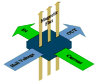
Experiment 3: The Hall Effect
Hall effect:
where
I = current passing through semiconductor
B= Magnetic field applied perpendicular to current direction
d= thickness of semiconductor in direction of applied B-filed
n= density of mobile charge carriers (free electrons or holes)
e= charge of an electron
V_H= Hall voltage which is established by electrons being bent to the walls of the semiconductor
- Coulomb
- The amount of charge that flows through any cross section of a wire in 1 second if there is a steady current of 1 ampere in the wire.
Coulomb Force
Two charged object separated by a distance (d) will feel a force between them known as the coulomb force. The magnitude of this force has been experimentally shown to be
where
- F/m = a experimentally measured quantity satisfying the above relationship know as the permittivity of free space.
- charge of first object
- charge of second object
- distance between the charges
(Charles Augustin Coulomb first measured the attract and repulsive force between two charged objects using a torsion balance around 1785)
This force may be described in terms of an electric field E such that
Where
- F= force between the objects
Electric Field
Vector Field
- What is a vector field?
- A vector field is the association of each point in space with a direction (vector).
Example: Gravity. On the surface of the earth you observe that an apple will fall down to the ground. You can measure the magnitude of this force by observing the attraction much like how coulomb observed how two charges attract or repel each other. You can define a vector ( which points directly down and tell you the direction that an apple will accelerate if it is released. If you construct such that
- = acceleration of an apple towards the earth's surface when close to the earth's surface.
Where G= gravitational constant =
Electric Field Vector
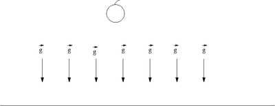
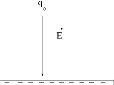
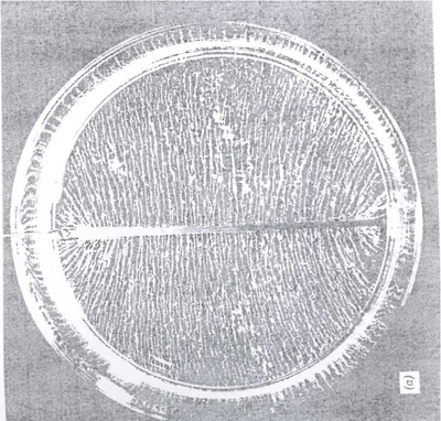
| Electric Field | Grass seeds in Insulating Liquid |
Instead of an apple of mass we can use a test charge of charge .
Instead an earth of mass we can use an object of charge .
We now define an Electric field Vector such that
- ;Notice the direction tells you which way a positive charge will move
- Note
- The definition of requires that the magnitude of the test charge approach zero, because the test charge can disturb the electric field we are actually trying to determine.
Lines of Coulomb Force
Once you know the Electric Vector Field you know the force on any charge placed in that field simply by
In other words, the tangent to the direction of the Force vector indicates the direction of the vector field .
- Unfortunately, charge can be either positive or negative whereas mass is always a positive quantity so the above uses the convention of a positive (test) charge.
Electric potential
The Electric potential (V) is a scalar which may be used to describe Electric Fields as well.
A charge which moves along an electric field line is having work done on it by an electric field.
Electric Potential Energy
From the work energy theorem, Work is equal to the change in energy of a system
- Kinetic Energy
The work done moving a change along an electric field line is
Potential Energy
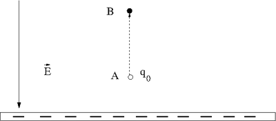
Let's say you lift a unit of POSITIVE charge (q) from location A above a sheet of negative charge to a higher location B.
- Note
- This is just like the gravitational example of walking up a flight of stairs.
You will need to apply a force on the positive charge to lift it up because the negatively charge sheet is attracting it (like the earth attracts your mass as you walk up a flight of stairs). For simplicity, let's assume you move at a constant velocity or no acceleration. In other words the attractive coulomb force is balanced by the force you use to push the positive charge to a higher location above the negatively charged infinite sheet. (For a more exact calculation you would exert a Force greater then qE to accelerate the charge to a velocity and then exert and equal but opposite force to de-accelerate the charge and bring it to rest; but all this cancels out so lets ignore it)
Potential Energy
: The applied force is directed opposite to the Electric field but in the same direction as the displacement
- = Potential Energy Difference
- Note
- The work done by the electric field is negative (the force from the electric field is opposite to the direction of motion).
Work Energy theorem :
If a conservative force is involved then :
Voltage (Electric Potential)
The Electric Potential Difference
The change in the potential depends on the sign of q_0
Positive (Negative) charge '''naturally''' goes from higher (lower) potential
to lower (higher) voltage.
 Voltage decreases(increases) when positive charge travels parallel(anti-parallel)
 to the electric field.
When you measure the electric potential (Voltage) you are actually measuring a potential difference V with respect to some point that is customarily chosen to be zero.
Remember this when you place the black probe of your voltmeter onto some
conducting point. The black probe might not be at "ground".
If you define the potential to be zero and move the charge a distance then the voltage is given by
Units
Electromotive Force(emf)
An electromotive force is used to describe the external work expended per unit of charge to produce an electric potential difference across two open-circuited terminals.
Battery
A battery uses a chemical reaction to separate atoms into ions and push electrons onto the negative terminal. The terminal of a battery are usually made out of two different metal electrodes separated by a solution/paste containing ions called the "electrolyte".
Ex: Carbon and zinc electrodes separated by ammonium chloride results in a chemical reaction which generates a 1.5 Volt potential difference between the carbon and zinc electrodes. This is called a cell. From cells you can make batteries by tying cells in series or parallel.
| Bat. Type | Cell emf (V) | characteristic |
| Carbon-Zinc | 1.5 | flashlight battery, voltage drops slowly with time |
| Alkaline-Maganeses | 1.5 | long lasting lasting flashlight battery, high current capacity, voltage drops gradually |
| Nickel-cadmium | 1.25 | rechargeable flashlight battery |
| Lead-acid | 2.6 | car battery, high currents, rechargeable, sufluric acid electrolyte |
| Silver Oxide | 1.5 | hearing aids and wathes, low current, constant voltage |
| Mercury | 1.35 | sudden voltage drops, indoor equipment. |
Notice the battery is an isolated voltage source. This means the definition of zero potential can be made at any one point in a circuit with one battery. Because the battery is using a chemical reaction, the electrons come from inside the battery and are not pulled or pushed from the earth (a ground).
As soon as you use the battery the emf changes and is called a voltage because of the internal resistance of the battery (see Lab 1). The voltage rating of the battery represents its "open-circuit" voltage; the voltage when it is not connected.
Unfortunately, batteries have an internal voltage which is only negligible if the external circuits resistance is much larger then the battery's internal resistance. When a battery is "dead" its internal resistance has become equivalent to the circuit the battery is trying to drive (flashlight). The chemical reaction has ceased to effectively pump electrons onto the terminal and as a result "resists" current flow.
Current
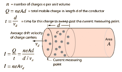
Definition
Sample calculation of electron drift velocity:
if
- area of wire
- length element of wire
then
- total charge in wire of length element
Assume you are running 3 Amps through a 1mm diameter wire of copper.
A= 63.546 g/mol
- The electron drift velocity is slow
BUT when I turn on my house light switch the light turns on quickly and not in hours.
Signal speed is c, speed of light (usually < 0.9 c, v_{RG-58U} =0.66 c): Add an electron on one end of the wire and the coulomb force is transmitted at close to the speed of light to the other end of the wire. The speed is less than light due to the interaction of the electrons in the wire medium.
Convention
Current indicates the direction a positive charge carrier would travel when subject to the given Electric field/Potential difference.
Resistance
General Properties
A resistor is basically a parallel piped of some material (usually Carbon) which has a conductor on each end.
A common analogy is to think of current flowing through a wire like water flowing through a pipe.
The longer the pipe the harder it is to push water through it.
The bigger the pipe, the easier it is to push water through it.
As a result of this physical observation you have that
where
- resistivity = constant of proportionality
Resistivity is a bulk property of matter such that a good conductor has a small value or resistivity (large value of conductivity) whereas bad conductors have large resistivity values.
Ex: Low resistivity= metals, plasmas, salt solutions, humans
High resisitvity= wood, rubber, plastic, glass, quartz
Convention
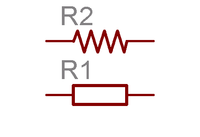
In circuits, a resistor is denoted using the symbol
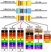
Resistor packages are labeled with the color coding below
| Color | value | |
| black | 0 | |
| brown | 1 | |
| R | Red | 2 |
| O | Orange | 3 |
| Y | Yellow | 4 |
| G | Green | 5 |
| B | Blue | 6 |
| V | Violet | 7 |
| gray | 8 | |
| white | 9 |
Typical resistors have three colors close to each other on one side.
The resistance is given by
If the tolerance is given it will appear as a single color line on the opposite side of the three color lines
Tolorance = color of fourth band usually
- Gold = \pm 5%
- Silver = \pm 10%
- No color = \pm 20%
Ohm's Law
- resistance is a constant
- = constant
Ohm's law is a statement the the resistant of a material is constant.
- Ohms law does not hold for all materials, (tunnel diode).
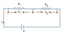
Resistors in Series
Resistors in series have the same current passing through them because of current conservation
using Ohm's Law
Resisters in series add
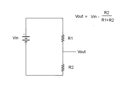
Voltage Divider
Consider the two resistors in series below
What is the ratio of to
Ohm's Law
so
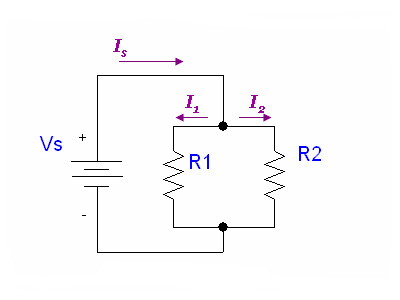
Resistors in parallel
For resistors in parallel
Ohm's Law says
Conservation of current says
Power
As shown before
Potential energy = = charge Voltage
Power =
Parallel or Series Light bulbs?
Light bulbs are basically resistors so hot that they give off light.
If you have 1 battery and a bunch of lights should you wire the light up in parallel or series to have the same amount of light come out of each light bulb?
If in series then the voltage drops in half across each bulb
If in parallel then each bull
Current is the same through each resistor and the voltage drop is the same so
- Wire those Xmas lights in parallel
Ideal/Real battery
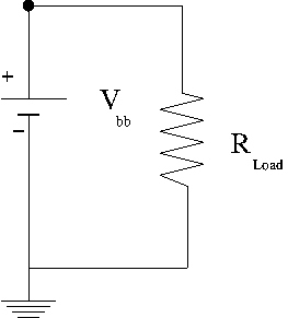
In an ideal battery you close the switch on a circuit, something complicated happens, then you reach a steady state current. An ideal battery will maintain a constant potential but not a constant current.
A real battery has an internal resistance such that a terminal voltage is supplies after there is a voltage drop within the battery due to its internal resistance. A battery "dies" because the internal resistance increases so much that the terminal voltage drops to zero preventing electrons from being pushes around outside the battery. The internal resistance increases when the chemical interactions inside the battery start to decrease.
= terminal voltage when there is no current in the external circuit being driven
| Ideal Battery | Real Battery |
Kirchhoff's Laws
Loop Theorem/ Voltage Law/Conservation of Energy
"Around any closed loop circuit, the algebraic sum of all the voltage drops must equal zero."
Real battery example
In the real battery example above you have a voltage source with two resistors in parallel.
Convention for current direction
Positive current flows into the positive side (higher voltage) of a resistor and out the negative side (lower potential) side.
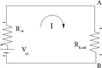
The arrow in the above picture identifies the direction of "positive" current. You should try to follow the direction of positive current when you define a loop to traverse the circuit and apply the loop theorem.
If I begin my loop on the positive terminal of the battery with , then the first voltage drop I encounter as I traverse the circuit clockwise is the battery's internal resistor . I then encounter a voltage drop across the load resistor R_{load} before completing my loop around the circuit.
Algebraically the voltage drop may be written as
The largest voltage drop occurs when since at any given time is a constant (though it increases with battery life until the battery is no longer able to drive the circuit).
- Note
- The highest current occurs when is the smallest. If you plot (the voltage measured across the battery terminal) as a function of where the current is increased by decreasing the value of then you will see a line with a y-intercept equivalent to and a slope equivalent to.
(see EIM Lab 1 Lab_1_TF_EIM)
Current Law/Conservation of Charge
"At any junction of wires in a circuit, the sum of all currents entering the junction is exactly equal to the sum of all currents leaving the junction."
Voltage Divider example
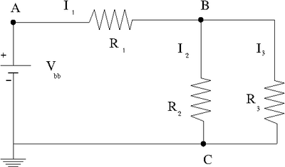
Consider the circuit below
An algebraic equation representing conservation of current at the junction can be written as
Applying conservation of energy (Voltage loop theorem) to the circuit in 2 loops we would write
The above description results in a system of 3 equations and 7 variables . A solution exists if there are only 3 unknowns or less.
Equivalent Circuit
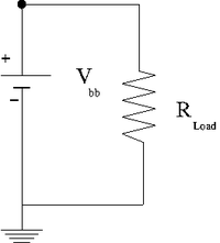
In the above voltage divider circuit, one could write an equivalent circuit by simplifying the resistors in series and parallel into one resistor.
where
Then
Find currents when Resistances are known
Returning to the system of 3 equations and 7 variables we can conclude that the voltage must be known as well as the resistances in order to determine the currents.
The system of equations may be written
You can solve the above for , , and by algebraic manipulation or Matrix Methods (determinant or inversion/Gauss-Jordan elimination)
- Matrix Method
Solutions exist as long as
- Method of Determinants
- : :
- Matrix Inversion/Gauss-Jordan elimination
If and are vectors and is a matrix such that
then one can find if and are known by using the following matrix math
Use Guass-Jordan elimination to find
. . .
Convention summary
1.) Decide on a loop and current direction. Don't worry if you get negative signs, they mean that the direction you chose was wrong.
2.) If you loop past a resistor in the direction of current then you add (-IR) if it is opposite the current you add (+IR)
3.) If you loop past an emf from the negative terminal to the positive terminal then you add (+V) if you first hit the positive terminal then you add (-V)
- Hints
- Try to simplify the circuit as much as possible by combining similar element that are in series or parallel
- Apply the junction and loop rules until the number of equations equals the number of unknowns
- solve the equations simultaneously
