Difference between revisions of "MiniDC Signals 10-0-07"
| (One intermediate revision by the same user not shown) | |||
| Line 21: | Line 21: | ||
The Scintillator mounted on top of the Chamber was set to -900 Volts | The Scintillator mounted on top of the Chamber was set to -900 Volts | ||
| − | Below is a scope picture representing the observation of a coincidence event between a particle which passed through both the top scintillator and the Mini Drift Chamber. The scope was triggered on the scintillator output. The top trace is the output of the drift chamber from one of the sense wires capacitively coupled to the scope and terminated in | + | Below is a scope picture representing the observation of a coincidence event between a particle which passed through both the top scintillator and the Mini Drift Chamber. The scope was triggered on the scintillator output. The top trace is the output of the drift chamber from one of the sense wires capacitively coupled to the scope and terminated in 50 Ohm. The bottom trace is the fast output from the Scintillator. |
[[Image:MiniChamber_CosmicCoincidence_10-9-07.jpg | 400 px]] | [[Image:MiniChamber_CosmicCoincidence_10-9-07.jpg | 400 px]] | ||
Latest revision as of 19:50, 23 October 2007
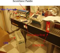
Signals were observed in the LDS on the Mini DC prototype sense wires capacitively coupled to a digital oscilloscope. The drift chamber was filled with a Ar/CO2 (75/25) gas mixture. A UPS was used to filter the line noise to the scope and NIM bin housing the Power supply. The noise level was 40 mV peak-to-peak when I started and was cut in half in the end after adding the UPS and a grounding strap between the chamber and the scope. The grounding strap was the most effective at reducing the noise.
The apparatus
The following Voltages were established on the Drift chamber wires
| HV settings | |
| Wire | Volts |
| Sense | 1800 |
| Field | -750 |
| Guard | 750 |
The Scintillator mounted on top of the Chamber was set to -900 Volts
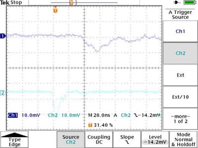
Below is a scope picture representing the observation of a coincidence event between a particle which passed through both the top scintillator and the Mini Drift Chamber. The scope was triggered on the scintillator output. The top trace is the output of the drift chamber from one of the sense wires capacitively coupled to the scope and terminated in 50 Ohm. The bottom trace is the fast output from the Scintillator.
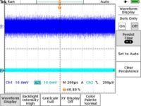
Noise Level Measured by scope in infinite persistance mode indicate that the Mini Prototype with plastic feedthroughs (Plastica) has noise levels spanning +/- 10 mV (10 Mv peak-to-peak). A PMT connected to a scintillator shows noise levels around+/- 2 mV.
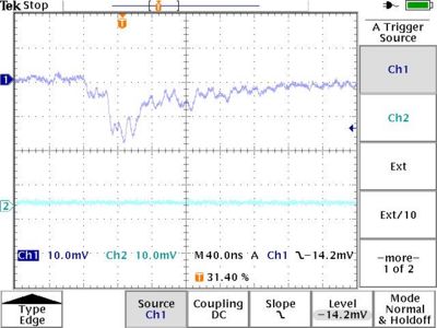
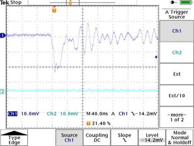
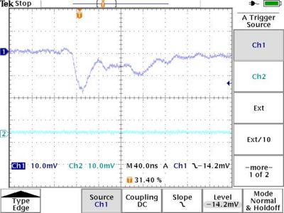
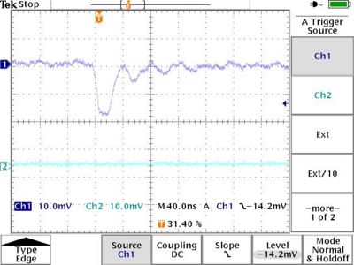
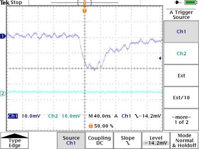
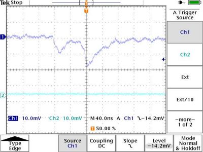
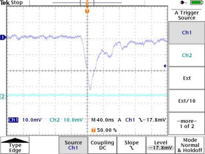
A few characteristic scope pictures of events triggered on the chamber output. The trigger threshold was set to ~-14 mV for all but the last picture which was set at -17 mV. Signals below -14 mV are beyond the detector noise measured above and considered ionization events.
