Difference between revisions of "R3"
| (149 intermediate revisions by 2 users not shown) | |||
| Line 1: | Line 1: | ||
| − | + | A description of the Region 3 (RIII) Design for CLAS12 | |
| + | |||
| + | =Press Releases= | ||
| + | |||
| + | Last Story was on September 23, 2013 in the ISJ "High Tech Project: ISU building chambers for Jefferson Lab detector upgrade" by jimmy handcock | ||
| + | |||
| + | http://idahostatejournal.com/members/high-tech-project-isu-building-chambers-for-jefferson-lab-detector/article_2e10e73e-26e5-11e3-9d2b-0019bb2963f4.html | ||
| + | |||
| + | Text for new Story | ||
| + | |||
| + | taylandy@isu.edu | ||
| + | |||
| + | It has been fours years since Idaho State University was awarded a half million dollar grant to build a set of precision devices called drift chambers. The devices built by ISU were commissioned last week and are now ready be used for the next decade by scientists from around the world. | ||
| + | |||
| + | Supported an ISU clean room | ||
| + | |||
| + | trained locals as technicians who have gone on to ON semiconductor. | ||
| + | |||
| + | Exposed ISU students to these devices. | ||
| + | |||
| + | = [[progress reports]] = | ||
| + | |||
| + | =presentation= | ||
| + | |||
| + | [[Media:29.Oct.08]] | ||
| + | |||
| + | = Timeline= | ||
| + | {| border="1" |cellpadding="20" cellspacing="0 | ||
| + | |- | ||
| + | |Description || Start Date || End Date || New End Date | ||
| + | |- | ||
| + | | PDR: Preliminary Design Review: 3-D models || 5/28/07 || 9/24/07 || 3/31/08 | ||
| + | |- | ||
| + | | [[DDP:Detailed Design Phase: Drawing and Assembly Package]] || 10/8/07 || 3/10/08 || 5/12/08 | ||
| + | |- | ||
| + | | [[PFD:Production_of_Fabrication_Drawings]] || 4/14/08|| 9/22/08 || 9/22/08 | ||
| + | |} | ||
| + | |||
=Conceptual Design= | =Conceptual Design= | ||
| − | ==Dimensions== | + | |
| − | ==Design | + | The location of Region III on this drift chamber can be viewed as<br> |
| − | = | + | [[Image:basic_Concept_one.jpg]] |
| − | ==Endplate without | + | |
| − | == | + | Region III is assembled with 6 Eqi-shaped pieces. Each of these pieces resembles a Pizza slice which together forms the whole chamber. |
| + | |||
| + | A view of the 6 piece assembly can be viewed as | ||
| + | [[Image:R3AllSectors.jpg]] | ||
| + | |||
| + | |||
| + | Each of these pieces is made of 3 kinds of plates. | ||
| + | |||
| + | 1. Nose Plate (1 No.) | ||
| + | |||
| + | 2. End Plate (2 No’s) | ||
| + | |||
| + | 3. Face Plate (1 No.) | ||
| + | |||
| + | A Sample assembly of the slice can be Viewed as | ||
| + | |||
| + | [[Image:basic_Concept_Three.jpg]] | ||
| + | |||
| + | |||
| + | '''End Plate:''' | ||
| + | |||
| + | There are 2 end plates for each slice which are attached opposite to each other. There are several holes on each end plate through which sets of wires are passed and connected to both end plates of a particular slice. The whole area in which holes are drilled on each End plate can be further divided into 2 areas; upward wire area and Downward wire area. A wire from upward wire area of end plate ‘A’ is drawn to the downward wire area in the opposite end plate ‘B’ and vice versa. Both these wires are angled at 6 degrees to the imaginary midline, which passes through the Nose plate and the Face Plate of each slice. | ||
| + | End plate can be Viewed as | ||
| + | |||
| + | [[Image:End_Plate_View.jpg | 400 px]] | ||
| + | |||
| + | '''Nose Plate:''' | ||
| + | |||
| + | This is the place which forms the base for each slice. Both the end plates are attached at the opposite ends of the Nose plate. The angled end of the end plates are attached to this nose plate, so that the end plates are projected at an angle in 3-D. | ||
| + | |||
| + | |||
| + | '''Back plate:''' | ||
| + | |||
| + | Back plate is the top plate which holds the end plate together on the top side. | ||
| + | |||
| + | =Design criteria= | ||
| + | |||
| + | The Design Criteria is to develop all the necessary dimensions from the known dimensions. | ||
| + | |||
| + | The known dimensions are | ||
| + | |||
| + | |||
| + | '''• Distance from target to first sense wire plane along a ray which is normal to the end plate = 4746.5 mm''' | ||
| + | |||
| + | '''• Chamber Tilt Angle = 25 Degrees''' | ||
| + | |||
| + | '''• Maximum Scattering Angle = 45 Degrees''' | ||
| + | |||
| + | '''• Minimum Electron Scattering angle = 5 Degrees''' | ||
| + | |||
| + | '''• Distance between the two Adjacent Pieces = 160 mm''' | ||
| + | |||
| + | |||
| + | The Definition of these given Dimensions can be viewed in the following pictures | ||
| + | |||
| + | [[Image:Definition_Of_Terms_One.jpg | 500 px]] | ||
| + | [[Image:Definition_Of_Terms_Two.jpg | 500 px]] | ||
| + | |||
| + | |||
| + | Theses known dimensions are used in the determination of the remaining dimensions of the chamber. | ||
| + | |||
| + | =Dimensions= | ||
| + | ==End Plate== | ||
| + | Dimensions of the End Plate can be Viewed Below<br> | ||
| + | [[Image:end_plate_dimensions.jpg | 500 px]] | ||
| + | |||
| + | ==Back Plate== | ||
| + | |||
| + | ==Nose Plate== | ||
| + | |||
| + | |||
| + | |||
| + | =Preliminary Design Phase (9/24/07)= | ||
| + | ==Design== | ||
| + | |||
| + | |||
| + | The endplate is a composite material composed of an inner polyerethane foam core with steel sheets glued to the largest area sides. The endplate, while made entirely of this composite, has a large number of holes in two central region through which the drift chamber wires are supported. To account for the effects of these holes the composite is defined in terms of two materials. Material 1 represents the composite material without holes while Material 2 has a density to reflect the presence of drilled holes. | ||
| + | |||
| + | The long sides of the endplate composite material have two support structures. On one side, carbon fiber rods (Material 3) are placed to help reduce reflections. On the other side a Hexcell foam impregnated with carbon fiber (Material 4) is used as a backing when all four sides of the drift chamber are assembled. | ||
| + | |||
| + | ===Material and cross section of drift chamber frames, endplates, back plates, and nose plates=== | ||
| + | ====Endplate material==== | ||
| + | |||
| + | #Polyeurethane Foam | ||
| + | ## R3 Design specification: General Plastics Mfg. Co., "LAST-A-FOAM", FR-3700 | ||
| + | ## [http://ipnweb.in2p3.fr/~rdd/publications/RDD_2007_01_CLAS_Preshower_mech_analysis.pdf Youngs modulus: 140 MPa ] | ||
| + | ## Density 240 kg/<math>m^3</math> | ||
| + | #Stanless steel plates | ||
| + | ##0.048 inch thick plates on both sides of Foam | ||
| + | ## Youngs Modulus= | ||
| + | ## Density = | ||
| + | |||
| + | ==== Downstream window Material==== | ||
| + | #Hexcell Honeycomb foam HRH 10-1/8 -1.8 | ||
| + | ##0.010 (Skin 1) + 1.520 (Core) + 0.010 (Skin 2) inches in thickness | ||
| + | ## impregnated wih graphite fabric | ||
| + | ## HRH-10 is the material name | ||
| + | ## 1/8 represents the cell size (diameter between opposing flat section) | ||
| + | ##Density= 1.8 lb/<math>ft^3</math> | ||
| + | ## Young's Modulus= | ||
| + | |||
| + | ===Wire hole patterns and feedthrough details=== | ||
| + | |||
| + | With a total of 112 sense wires and 44 wire layers, we exect to drill 4,928 precision holes in the drift chamber endplate. | ||
| + | |||
| + | A Basic View of the Hole on the End Plate with the Feedthrough can be Shown Below | ||
| + | |||
| + | [[Image:Hole_And_Feed_Through.jpg]] | ||
| + | |||
| + | ===Method for attaching/securing wires=== | ||
| + | ===Support bracings, if needed=== | ||
| + | ===Lifting attachments and supports=== | ||
| + | ===Assembly fixture=== | ||
| + | |||
| + | ==Mechanical Analysis== | ||
| + | === ANSYS Model=== | ||
| + | Ansys is used as the modeling and analysis tool. | ||
| + | Several cases both in 2-D and 3-D models will be analyzed. | ||
| + | |||
| + | In this explanation. 2-D model is itself is a 3-D model. However, the deflection of a single end plate will be analyzed with some assumptions | ||
| + | |||
| + | === 2-D Model=== | ||
| + | |||
| + | This 2-D model is basically a 3-D model of the end plate itself. | ||
| + | Several orientations have been analyzed. | ||
| + | The description of this 2-D model can be observed below. | ||
| + | [[Image:2-D.jpg | 400 px]] | ||
| + | [[Image:2-D_materials.jpg]] | ||
| + | |||
| + | ==='''''2-D model results of several orientations and cases are tabulated below'''''=== | ||
| + | [[Image:2-D_results.jpg]] | ||
| + | |||
| + | ===3-D Model=== | ||
| + | This 3-D model is a one (out of six) 3-D piece model.<br> | ||
| + | [[Image:3-Dim.jpg | 600 px]] | ||
| + | [[Image:3d-loads.jpg]] | ||
| + | [[Image:results_3d.jpg]] | ||
| + | |||
| + | ===Refined 3-D Model with Mylar sheet=== | ||
| + | |||
| + | Gas pressure inside the chamber will be just above 1 atm in order to have a constant flow of ArCo2. The average differential pressure is expected to be about 0.04 of an inch of water (<math>Atm , lbs/in^2</math>). The peak pressure differential is assumed to be 5 times higher. | ||
| + | |||
| + | =Presentation= | ||
| + | |||
| + | == Drawings== | ||
| + | ==Vendors== | ||
| + | #Hysol 9339 glue [[Image:Hysol9339glue.pdf]] is used for the endplates to glue the 0.048 inch thick Stanless steel plates to the Polyeurethane "LAST-A-FOAM", FR-3700 Foam. Vendor used for previous CLAS chambers: Dexter Corp., Adhesives & Structural Materials Division, 465 Marietta, GA 30064, PH. 404-427-1567 | ||
| + | #Epon is the glue used for the feedthroughs, potting pins, and to seal connections. The previous CLAS drift chambers used the Epon 828 resin with Versamid 140 hardener in a ratio of 100:44.5. Other types may have more plasticisers that can out-gas. Our source for Epon was E.V. Roberts and Associates, Inc., 8500 Steller Drive, PO Box 868, Culver City, CA 90232, PH. 213-870-9561. | ||
| + | ===Provide materials=== | ||
| + | ===Perform fabrication=== | ||
| + | |||
| + | = References= | ||
| + | #[http://clasweb.jlab.org/wiki/index.php/12GeV_DC_Meeting_Minutes_and_Notes JLab's CLAS12 DC Meeting wiki] | ||
| + | #[http://www.jlab.org/Hall-B/secure/clas12/RIII/ISU_Design/Progress.html R3 status page at JLAB] | ||
| + | # CLAS detector NIM article [[Media:NIM_A449.pdf]] | ||
| + | # Mac's CLAS 12 tracking design writeup May 15 , 2005 [[Media:CLAS12-5-2005.pdf]] | ||
| + | #Mac's CLAS 12 tracking design writeup Jan. 1, 2007 [[Media:CLAS12-1-2007.pdf]] | ||
| + | |||
| + | =JLAB visit= | ||
| + | == 9/17/09== | ||
| + | |||
| + | === Task list=== | ||
| + | |||
| + | # review construction of R1 prototype chamber | ||
| + | # compare Material descriptions | ||
| + | # retrive Hexcell sample of R3 outer Shell | ||
| + | # Review ISU's current ANSYS model with bob williams | ||
| + | |||
| + | # Search for any R3 endplate remnants from current CLAS | ||
| + | # Make sure we have necessary connector for Baby chamber preamp output to out amplifiers | ||
| + | # can we borrow a VME ADC | ||
| + | |||
| + | # Check parameters of polyurethane foam listed above with vendors | ||
| + | # get Young's modulus for outer shell | ||
| + | # first deflection picture of endplate with/without carbon fiber rods | ||
| + | |||
| + | =Presentation= | ||
| + | == Dec, 11, 2007 == | ||
| + | |||
| + | =Reports= | ||
| + | ==Draft for the base End plate Deflection analysis== | ||
| + | [[image:Draft_1_end_plate_deflection_analysis.pdf]] | ||
| + | ==2-08 Report== | ||
| + | [[R3DC_Report_2-08]] | ||
| + | |||
| + | |||
| + | |||
| + | [http://www.iac.isu.edu/mediawiki/index.php/Hall_B Go Back] | ||
Latest revision as of 23:03, 8 February 2017
A description of the Region 3 (RIII) Design for CLAS12
Press Releases
Last Story was on September 23, 2013 in the ISJ "High Tech Project: ISU building chambers for Jefferson Lab detector upgrade" by jimmy handcock
Text for new Story
taylandy@isu.edu
It has been fours years since Idaho State University was awarded a half million dollar grant to build a set of precision devices called drift chambers. The devices built by ISU were commissioned last week and are now ready be used for the next decade by scientists from around the world.
Supported an ISU clean room
trained locals as technicians who have gone on to ON semiconductor.
Exposed ISU students to these devices.
progress reports
presentation
Timeline
| Description | Start Date | End Date | New End Date |
| PDR: Preliminary Design Review: 3-D models | 5/28/07 | 9/24/07 | 3/31/08 |
| DDP:Detailed Design Phase: Drawing and Assembly Package | 10/8/07 | 3/10/08 | 5/12/08 |
| PFD:Production_of_Fabrication_Drawings | 4/14/08 | 9/22/08 | 9/22/08 |
Conceptual Design
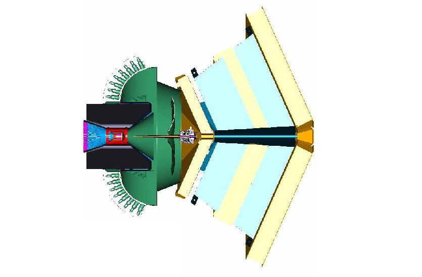
The location of Region III on this drift chamber can be viewed as
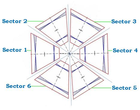
Region III is assembled with 6 Eqi-shaped pieces. Each of these pieces resembles a Pizza slice which together forms the whole chamber.
A view of the 6 piece assembly can be viewed as
Each of these pieces is made of 3 kinds of plates.
1. Nose Plate (1 No.)
2. End Plate (2 No’s)
3. Face Plate (1 No.)
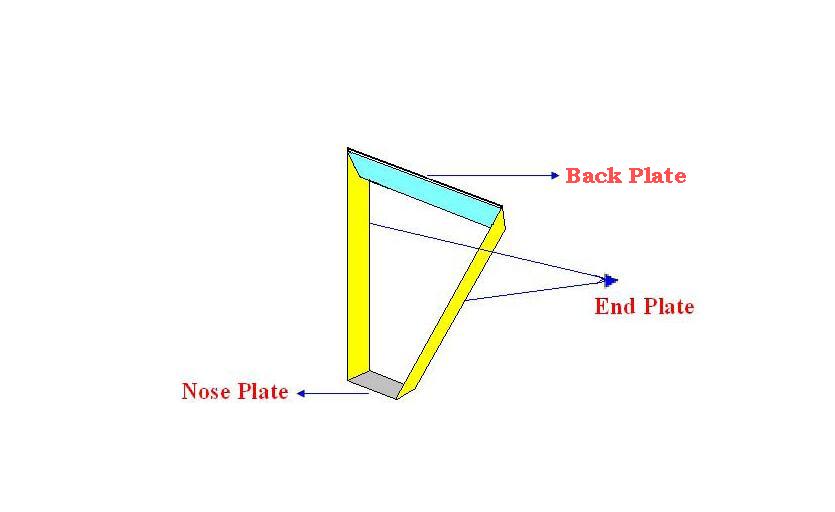
A Sample assembly of the slice can be Viewed as
End Plate:
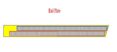
There are 2 end plates for each slice which are attached opposite to each other. There are several holes on each end plate through which sets of wires are passed and connected to both end plates of a particular slice. The whole area in which holes are drilled on each End plate can be further divided into 2 areas; upward wire area and Downward wire area. A wire from upward wire area of end plate ‘A’ is drawn to the downward wire area in the opposite end plate ‘B’ and vice versa. Both these wires are angled at 6 degrees to the imaginary midline, which passes through the Nose plate and the Face Plate of each slice. End plate can be Viewed as
Nose Plate:
This is the place which forms the base for each slice. Both the end plates are attached at the opposite ends of the Nose plate. The angled end of the end plates are attached to this nose plate, so that the end plates are projected at an angle in 3-D.
Back plate:
Back plate is the top plate which holds the end plate together on the top side.
Design criteria
The Design Criteria is to develop all the necessary dimensions from the known dimensions.
The known dimensions are
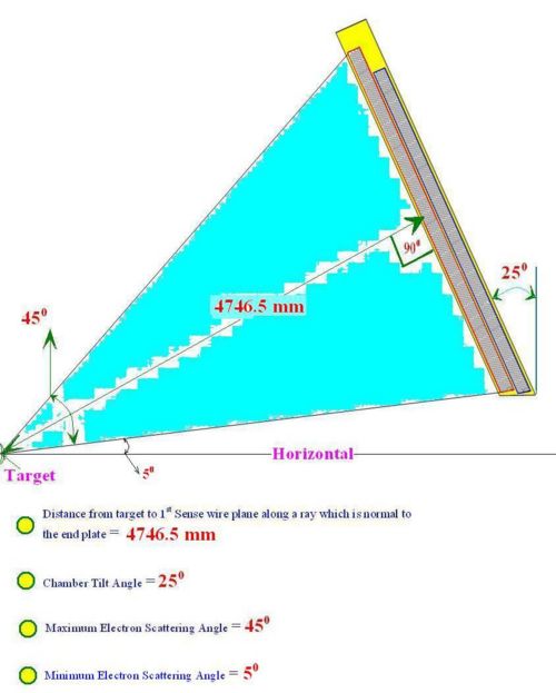
• Distance from target to first sense wire plane along a ray which is normal to the end plate = 4746.5 mm
• Chamber Tilt Angle = 25 Degrees
• Maximum Scattering Angle = 45 Degrees
• Minimum Electron Scattering angle = 5 Degrees
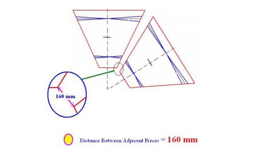
• Distance between the two Adjacent Pieces = 160 mm
The Definition of these given Dimensions can be viewed in the following pictures
Theses known dimensions are used in the determination of the remaining dimensions of the chamber.
Dimensions
End Plate
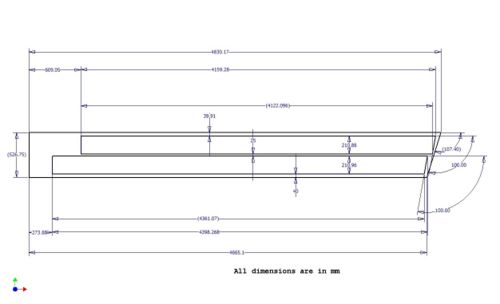
Dimensions of the End Plate can be Viewed Below
Back Plate
Nose Plate
Preliminary Design Phase (9/24/07)
Design
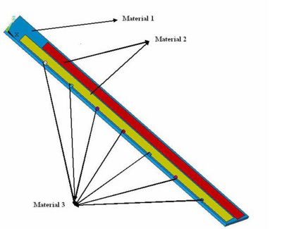
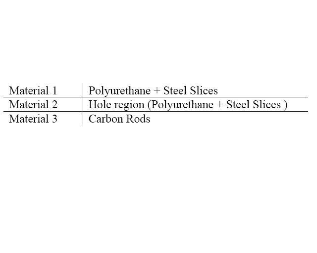
The endplate is a composite material composed of an inner polyerethane foam core with steel sheets glued to the largest area sides. The endplate, while made entirely of this composite, has a large number of holes in two central region through which the drift chamber wires are supported. To account for the effects of these holes the composite is defined in terms of two materials. Material 1 represents the composite material without holes while Material 2 has a density to reflect the presence of drilled holes.
The long sides of the endplate composite material have two support structures. On one side, carbon fiber rods (Material 3) are placed to help reduce reflections. On the other side a Hexcell foam impregnated with carbon fiber (Material 4) is used as a backing when all four sides of the drift chamber are assembled.
Material and cross section of drift chamber frames, endplates, back plates, and nose plates
Endplate material
- Polyeurethane Foam
- R3 Design specification: General Plastics Mfg. Co., "LAST-A-FOAM", FR-3700
- Youngs modulus: 140 MPa
- Density 240 kg/
- Stanless steel plates
- 0.048 inch thick plates on both sides of Foam
- Youngs Modulus=
- Density =
Downstream window Material
- Hexcell Honeycomb foam HRH 10-1/8 -1.8
- 0.010 (Skin 1) + 1.520 (Core) + 0.010 (Skin 2) inches in thickness
- impregnated wih graphite fabric
- HRH-10 is the material name
- 1/8 represents the cell size (diameter between opposing flat section)
- Density= 1.8 lb/
- Young's Modulus=
Wire hole patterns and feedthrough details
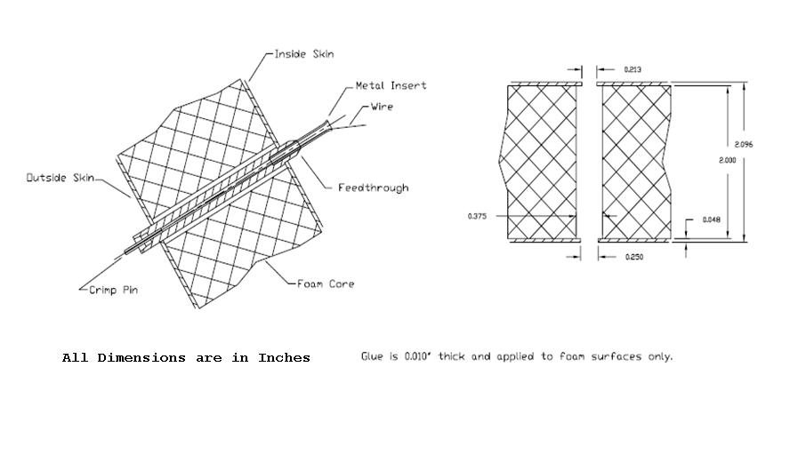
With a total of 112 sense wires and 44 wire layers, we exect to drill 4,928 precision holes in the drift chamber endplate.
A Basic View of the Hole on the End Plate with the Feedthrough can be Shown Below
Method for attaching/securing wires
Support bracings, if needed
Lifting attachments and supports
Assembly fixture
Mechanical Analysis
ANSYS Model
Ansys is used as the modeling and analysis tool. Several cases both in 2-D and 3-D models will be analyzed.
In this explanation. 2-D model is itself is a 3-D model. However, the deflection of a single end plate will be analyzed with some assumptions
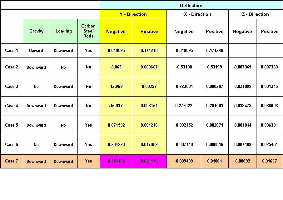
2-D Model
This 2-D model is basically a 3-D model of the end plate itself.
Several orientations have been analyzed.
The description of this 2-D model can be observed below.
2-D model results of several orientations and cases are tabulated below
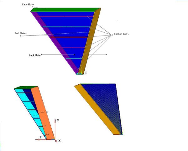
3-D Model
This 3-D model is a one (out of six) 3-D piece model.
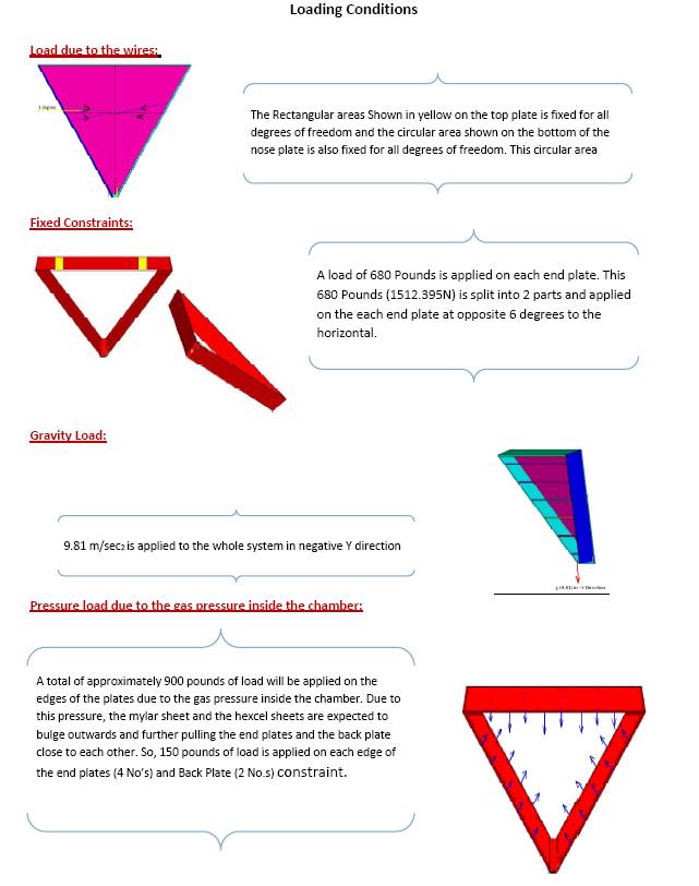
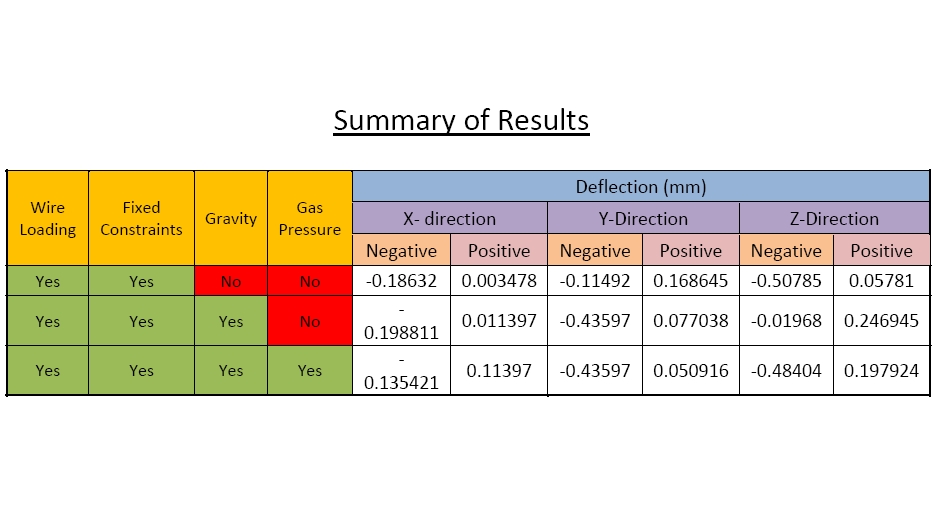
Refined 3-D Model with Mylar sheet
Gas pressure inside the chamber will be just above 1 atm in order to have a constant flow of ArCo2. The average differential pressure is expected to be about 0.04 of an inch of water (). The peak pressure differential is assumed to be 5 times higher.
Presentation
Drawings
Vendors
- Hysol 9339 glue File:Hysol9339glue.pdf is used for the endplates to glue the 0.048 inch thick Stanless steel plates to the Polyeurethane "LAST-A-FOAM", FR-3700 Foam. Vendor used for previous CLAS chambers: Dexter Corp., Adhesives & Structural Materials Division, 465 Marietta, GA 30064, PH. 404-427-1567
- Epon is the glue used for the feedthroughs, potting pins, and to seal connections. The previous CLAS drift chambers used the Epon 828 resin with Versamid 140 hardener in a ratio of 100:44.5. Other types may have more plasticisers that can out-gas. Our source for Epon was E.V. Roberts and Associates, Inc., 8500 Steller Drive, PO Box 868, Culver City, CA 90232, PH. 213-870-9561.
Provide materials
Perform fabrication
References
- JLab's CLAS12 DC Meeting wiki
- R3 status page at JLAB
- CLAS detector NIM article Media:NIM_A449.pdf
- Mac's CLAS 12 tracking design writeup May 15 , 2005 Media:CLAS12-5-2005.pdf
- Mac's CLAS 12 tracking design writeup Jan. 1, 2007 Media:CLAS12-1-2007.pdf
JLAB visit
9/17/09
Task list
- review construction of R1 prototype chamber
- compare Material descriptions
- retrive Hexcell sample of R3 outer Shell
- Review ISU's current ANSYS model with bob williams
- Search for any R3 endplate remnants from current CLAS
- Make sure we have necessary connector for Baby chamber preamp output to out amplifiers
- can we borrow a VME ADC
- Check parameters of polyurethane foam listed above with vendors
- get Young's modulus for outer shell
- first deflection picture of endplate with/without carbon fiber rods
Presentation
Dec, 11, 2007
Reports
Draft for the base End plate Deflection analysis
File:Draft 1 end plate deflection analysis.pdf
2-08 Report
