Difference between revisions of "Determining wire-theta correspondence"
| (51 intermediate revisions by the same user not shown) | |||
| Line 1: | Line 1: | ||
| − | <center><math>\ | + | <center><math>\underline{\textbf{Navigation}}</math> |
[[VanWasshenova_Thesis#Determining_wire-theta_correspondence|<math>\vartriangleleft </math>]] | [[VanWasshenova_Thesis#Determining_wire-theta_correspondence|<math>\vartriangleleft </math>]] | ||
| Line 14: | Line 14: | ||
<center>DC: Drift Chambers[https://www.jlab.org/Hall-B/clas12-web/specs/dc.pdf (specs)]</center> | <center>DC: Drift Chambers[https://www.jlab.org/Hall-B/clas12-web/specs/dc.pdf (specs)]</center> | ||
| + | |||
<center>DC Geometry[https://clasweb.jlab.org/wiki/images/d/d1/Dc12geom_doc.pdf (geom)]</center> | <center>DC Geometry[https://clasweb.jlab.org/wiki/images/d/d1/Dc12geom_doc.pdf (geom)]</center> | ||
| Line 26: | Line 27: | ||
! Definition | ! Definition | ||
|- | |- | ||
| − | | thtilt | + | ! thstereo |
| + | | 6 degrees | ||
| + | | Tilt of wires normal to sector midpoint | ||
| + | |- | ||
| + | ! thtilt | ||
| 25 degrees | | 25 degrees | ||
| Tilt relative to z | | Tilt relative to z | ||
|- | |- | ||
| − | + | ! dist2tgt | |
| 228.078 cm | | 228.078 cm | ||
| Distance from the target to the first guard wire plane along the | | Distance from the target to the first guard wire plane along the | ||
normal of said plane | normal of said plane | ||
|- | |- | ||
| − | + | ! th_min | |
| 4.694 degrees | | 4.694 degrees | ||
|Polar angle to the first guard wire’s (in the first guard wire plane) midpoint | |Polar angle to the first guard wire’s (in the first guard wire plane) midpoint | ||
| Line 41: | Line 46: | ||
mid-plane | mid-plane | ||
|- | |- | ||
| − | + | !wpdist | |
| 0.3861 cm | | 0.3861 cm | ||
| Distance between the wire planes | | Distance between the wire planes | ||
| Line 48: | Line 53: | ||
| − | At 25 degrees above the beam line direction, we can create a line that is perpendicular to the plane of the wires, which are at 65 degrees above the reverse beam line direction. This line will be a perpendicular line with respect to all parallel layers of wires with | + | At 25 degrees above the beam line direction, we can create a line that is perpendicular to the plane of the wires, which are at 65 degrees above the reverse beam line direction. This line will be a perpendicular line with respect to all parallel layers of wires with regards to the initial guard wire plane. We can use this geometry and '''dist2tgt''', which is the distance from the target to the first guard wire in the first guard wire plane, to calculate other distances. |
| − | [[File:GuardWireLocation.png| | + | [[File:GuardWireLocation.png|thumb|center|500px|alt=Geometry of Guard Wire Plane in DC|'''Figure 5.1.1:''' The distance and angles which are derived from the angle with respect to the beam line (thtilt) and the distance for the guard wire plane perpendicular bisector(dist2tgt). All distances and angles are for the midplane bisector.]] |
Using trigonometry, we can find the distance along the beam line to the intersection with the initial guard wire plane. | Using trigonometry, we can find the distance along the beam line to the intersection with the initial guard wire plane. | ||
| + | |||
<center><math>\frac{228.078\ cm}{cos\ 25^{\circ}}=251.6562\ cm</math></center> | <center><math>\frac{228.078\ cm}{cos\ 25^{\circ}}=251.6562\ cm</math></center> | ||
| − | The parallel planes of wires are shown in the | + | The wire planes in the DC are parallel to each other and separated by a constant distance wpdist. The parallel planes of wires are shown in the Figure 5.1.2 below. |
| + | |||
| + | |||
| + | |||
| + | [[File:Wires_parallel_all_types.png|thumb|center|500px|alt=Geometry of Guard Wire Plane in DC|'''Figure 5.1.2:''' The placement of the different wire planes in the DC as seen along the perpendicular bisector plane. ]] | ||
| + | |||
| + | [[File:Midpoint.png|thumb|center|500px|alt=Sector Midpoint|'''Figure 5.1.3:''' The placement of sector midpoint line. ]] | ||
| − | |||
The angle''' th_min''' is defined as the polar angle to the first guard wire’s (in the first guard wire plane) midpoint | The angle''' th_min''' is defined as the polar angle to the first guard wire’s (in the first guard wire plane) midpoint | ||
| − | where the wire mid-point is the intersection of the wire with the chamber mid-plane. The first guard wire can be found at 4.694 degrees above the beam line. This position can be taken as the starting position for the wire | + | where the wire mid-point is the intersection of the wire with the chamber mid-plane. The first guard wire can be found at 4.694 degrees above the beam line. This position can be taken as the starting position for the initial guard wire plane. The planes of each wire runs 65 degrees above the reverse beam direction. |
| + | |||
| + | |||
| + | [[File:1st_position.png|thumb|center|500px|alt=Geometry of Guard Wire Plane in DC|'''Figure 5.1.4:''' The distance and angles based on the 1st location of the lowest guard wire from the beam line along the DC sector bisector.]] | ||
| − | + | Using the law of sines, we can find the distance along the x' axis the 1st guard wire is from the beam line. | |
| − | |||
| + | <center><math>\frac{251.6562cm}{sin\ 110.306^{\circ}}=\frac{d_{x'}}{sin\ 4.694^{\circ}}\Rightarrow d_{x'}=21.9587cm</math></center> | ||
| − | |||
| − | Making a right triangle, | + | Making a right triangle, with the x' component as the hypotenuse, we find the x and z components |
| + | {| class="wikitable" align="center" | ||
| + | | style="background: gray" | <math>21.9587cm\ sin\ 65^{\circ}=19.914cm\ \hat{x}</math> | ||
| + | |} | ||
| − | |||
| − | <center><math>21. | + | <center><math>21.9587cm\ cos\ 65^{\circ}=9.2802cm</math></center> |
| − | + | {| class="wikitable" align="center" | |
| + | | style="background: gray" | <math>251.6562cm-9.2802cm=242.376cm\ \hat{z}</math> | ||
| + | |} | ||
| − | |||
| + | This gives the location of the first guard wire, in the plane of the foremost guard wires, at the midplane position to be <math>(19.914\ , 0\ , 242.376)</math> in the frame of the target. | ||
| − | |||
| + | Examining the geometry file, we can see that each plane, not just the plane of the sense wires, is separated by a distance of D=.3861 cm. Each wire placement is half way between each wires in the adjacent planes. Each sense wire is in the center of an equilateral hexagon as a result. We can use the geometry of the wire placements to find | ||
| − | |||
| + | <center><math>\alpha=\frac{D}{\cos(60^{\circ})}=2D</math></center> | ||
| + | |||
| + | |||
| + | Finding the separation distance between two adjacent sense wires | ||
<center><math>d=4(.3861\ cm)\cos(30^{\circ})=1.337\ cm</math></center> | <center><math>d=4(.3861\ cm)\cos(30^{\circ})=1.337\ cm</math></center> | ||
| − | [[File:DC_geometry_wires_copy.png| | + | <center> |
| + | [[File:800px-Hex.png|center|thumb|700px|alt=Geometry of Guard Wire Plane in DC|'''Figure 5.1.5:''' The separation between adjacent sense wires along the DC midplane bisector.]] | ||
| + | </center> | ||
| + | |||
| + | |||
| + | Using the fact that the outer sides of an equalateral hexagon are equal in length, we can find that the distance from the first guard wire, in the first guard wire plane, to the first sense wire, in the first sense wire plane, is | ||
| + | |||
| + | <center><math>r_{WRT\ 1st\ guard\ wire}=3(2D)=2.3166\ cm</math></center> | ||
| + | |||
| + | |||
| + | [[File:DC_geometry_wires_copy.png|center|thumb|700px|alt=Geometry of Guard Wire Plane in DC|'''Figure 5.1.6:''' The wire cells as seen from the DC midplane bisector.]] | ||
| + | |||
| + | |||
| + | Since an equilateral hexagon have interior angles of <math>120^{\circ}</math>, lines from the field wires that cross through the sense wire bisect the angle. The result is that each hexagon contains 6 equilateral triangles with interior angles of <math>60^{\circ}</math>. The rotation of the wire planes do not allow the distance from the first guard wire to the first sense wire to be orthogonal with respect to the frame of the target. Finding the perpendicular distance in the x direction we can create a right triangle with angles 65 and 90, implying the remaining angle of 25 degrees. | ||
| + | |||
| + | Using the distance from the first guard wire to the first sense wire and the angle found previously, | ||
| + | [[File:Tilt_position.png|center|thumb|500px|alt=Geometry of Guard Wire Plane in DC|'''Figure 5.1.7:''' The distance and angles to the 1st sense based on the geometry along the DC midplane bisector.]] | ||
| − | |||
The starting position for sense wires with respect to the first guard wire at midplane, can be found to be at: | The starting position for sense wires with respect to the first guard wire at midplane, can be found to be at: | ||
| + | |||
<center><math>2.3166\ cm\ \cos\ 5^{\circ}=2.3078\ cm\ \hat{x}</math></center> | <center><math>2.3166\ cm\ \cos\ 5^{\circ}=2.3078\ cm\ \hat{x}</math></center> | ||
| Line 121: | Line 157: | ||
| + | With respect to the target, this location becomes | ||
| + | |||
| + | {| class="wikitable" align="center" | ||
| + | | style="background: gray" | <math>19.9014\ cm+2.3078\ cm = 22.2092\ cm\ \hat{x}\equiv x_1</math> | ||
| + | |} | ||
| + | |||
| + | |||
| + | |||
| + | |||
| + | |||
| + | |||
| + | |||
| + | {| class="wikitable" align="center" | ||
| + | | style="background: gray" | <math>242.376cm\ +.2019\ cm =242.5779\ cm\ \hat{z}\equiv z_1</math> | ||
| + | |} | ||
Since the separation between adjacent sense wires is uniform and at a set angle of 25 degrees with respect to the beam line, we can use this fact to determine the angle theta each wire makes when measured from the vertex. | Since the separation between adjacent sense wires is uniform and at a set angle of 25 degrees with respect to the beam line, we can use this fact to determine the angle theta each wire makes when measured from the vertex. | ||
| + | |||
| + | [[File:DC_geom.png|center|thumb|500px|alt=Geometry of Guard Wire Plane in DC|'''Figure 5.1.8:''' The distance and angles between the first layer of sense wires based on the 1st sense wire location along the DC midplane.]] | ||
| − | |||
| Line 139: | Line 191: | ||
The new x and z coordinates for wire 2 can be found using the change in the components | The new x and z coordinates for wire 2 can be found using the change in the components | ||
| − | |||
| − | <center><math> | + | <center><math>x_2 \equiv x_1 + \Delta x</math></center> |
| + | |||
| + | |||
| + | <center><math>z_2 \equiv z_1 + \Delta z</math></center> | ||
This can be extended to any point along the same wire plane, starting from the coordinates for wire 1 minus the difference in position to the next wire crossing on the plane. | This can be extended to any point along the same wire plane, starting from the coordinates for wire 1 minus the difference in position to the next wire crossing on the plane. | ||
| − | |||
| − | <center><math>z_0 | + | <center><math>x_0 \equiv x_1 - \Delta x \equiv 22.2092\ cm\ - 1.212\ cm=20.9972\ cm</math></center> |
| + | |||
| + | |||
| + | <center><math>z_0 \equiv z_1 - \Delta z \equiv 242.5779\ cm\ +0.5652\ cm=243.1431\ cm</math></center> | ||
| − | <center><math>x=x_0+\Delta x\times\ n</math></center> | + | With this new starting point, a function dependant on the wire number can be derived |
| + | |||
| + | |||
| + | <center><math>x = x_0 + \Delta x\times\ n</math></center> | ||
| + | |||
| + | |||
| + | <center><math>z = z_0 + \Delta z\times\ n</math></center> | ||
| − | |||
The angle theta that the wire makes with the vertex is given by | The angle theta that the wire makes with the vertex is given by | ||
| Line 165: | Line 226: | ||
| − | <center><math>\ | + | <center><math>\theta_{wire\ 1}=\arctan\ .09155=5.2311^{\circ}</math></center> |
| − | |||
| − | |||
| − | |||
| − | |||
| Line 179: | Line 236: | ||
<center><math>z(n)=243.1431-0.5652\ n</math></center> | <center><math>z(n)=243.1431-0.5652\ n</math></center> | ||
| + | |||
<center><math>\tan{\theta}=\frac{20.9972+n1.212}{243.1431-n0.5652}\Rightarrow \tan{ \theta}=\frac{-959.637}{n - 430.189} - 2.14437 \Rightarrow 430.637 - n = \frac{959.637}{\tan{ \theta}+2.14437}</math></center> | <center><math>\tan{\theta}=\frac{20.9972+n1.212}{243.1431-n0.5652}\Rightarrow \tan{ \theta}=\frac{-959.637}{n - 430.189} - 2.14437 \Rightarrow 430.637 - n = \frac{959.637}{\tan{ \theta}+2.14437}</math></center> | ||
| − | <center><math>\Rightarrow n = \frac{-959. | + | <center><math>\Rightarrow n = \frac{-959.637}{\tan{ \theta}+2.14437}+430.189</math></center> |
| Line 189: | Line 247: | ||
| − | <center><math>\ | + | <center><math>\underline{\textbf{Navigation}}</math> |
[[VanWasshenova_Thesis#Determining_wire-theta_correspondence|<math>\vartriangleleft </math>]] | [[VanWasshenova_Thesis#Determining_wire-theta_correspondence|<math>\vartriangleleft </math>]] | ||
Latest revision as of 20:12, 15 May 2018
5.1.1 Determine a Wire-Theta Correspondence
To associate the hits with the Moller scattering angle theta, the occupancy plots of the drift chamber hits by means of wire numbers and layer must be translated using the physical constraints of the detector. Using the data released for the DC:
| Variable | Measurement | Definition |
|---|---|---|
| thstereo | 6 degrees | Tilt of wires normal to sector midpoint |
| thtilt | 25 degrees | Tilt relative to z |
| dist2tgt | 228.078 cm | Distance from the target to the first guard wire plane along the
normal of said plane |
| th_min | 4.694 degrees | Polar angle to the first guard wire’s (in the first guard wire plane) midpoint
where the wire mid-point is the intersection of the wire with the chamber mid-plane |
| wpdist | 0.3861 cm | Distance between the wire planes |
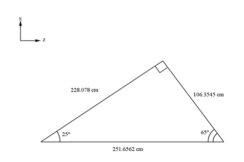
At 25 degrees above the beam line direction, we can create a line that is perpendicular to the plane of the wires, which are at 65 degrees above the reverse beam line direction. This line will be a perpendicular line with respect to all parallel layers of wires with regards to the initial guard wire plane. We can use this geometry and dist2tgt, which is the distance from the target to the first guard wire in the first guard wire plane, to calculate other distances.
Using trigonometry, we can find the distance along the beam line to the intersection with the initial guard wire plane.
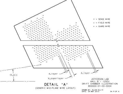
The wire planes in the DC are parallel to each other and separated by a constant distance wpdist. The parallel planes of wires are shown in the Figure 5.1.2 below.
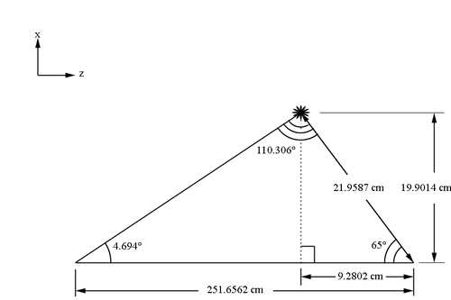
The angle th_min is defined as the polar angle to the first guard wire’s (in the first guard wire plane) midpoint
where the wire mid-point is the intersection of the wire with the chamber mid-plane. The first guard wire can be found at 4.694 degrees above the beam line. This position can be taken as the starting position for the initial guard wire plane. The planes of each wire runs 65 degrees above the reverse beam direction.
Using the law of sines, we can find the distance along the x' axis the 1st guard wire is from the beam line.
Making a right triangle, with the x' component as the hypotenuse, we find the x and z components
This gives the location of the first guard wire, in the plane of the foremost guard wires, at the midplane position to be in the frame of the target.
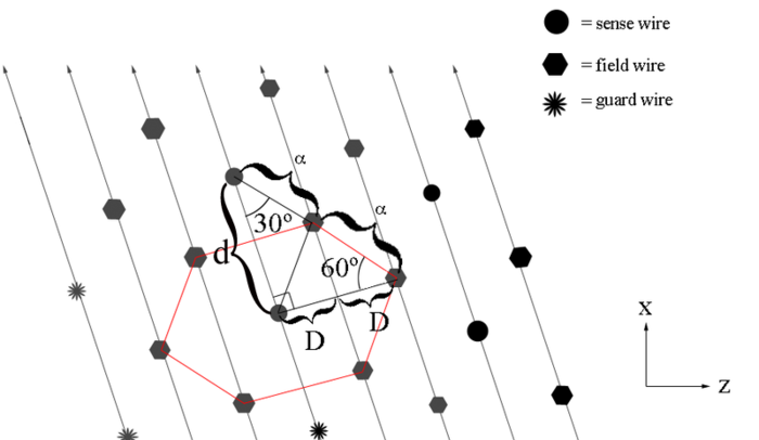
Examining the geometry file, we can see that each plane, not just the plane of the sense wires, is separated by a distance of D=.3861 cm. Each wire placement is half way between each wires in the adjacent planes. Each sense wire is in the center of an equilateral hexagon as a result. We can use the geometry of the wire placements to find
Finding the separation distance between two adjacent sense wires
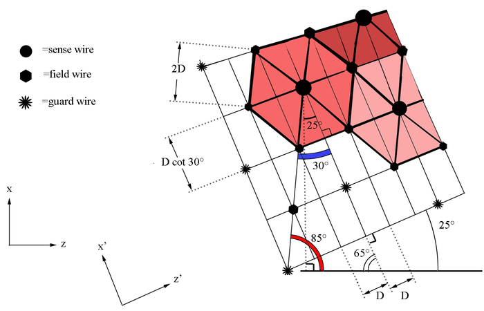
Using the fact that the outer sides of an equalateral hexagon are equal in length, we can find that the distance from the first guard wire, in the first guard wire plane, to the first sense wire, in the first sense wire plane, is
Since an equilateral hexagon have interior angles of , lines from the field wires that cross through the sense wire bisect the angle. The result is that each hexagon contains 6 equilateral triangles with interior angles of . The rotation of the wire planes do not allow the distance from the first guard wire to the first sense wire to be orthogonal with respect to the frame of the target. Finding the perpendicular distance in the x direction we can create a right triangle with angles 65 and 90, implying the remaining angle of 25 degrees.
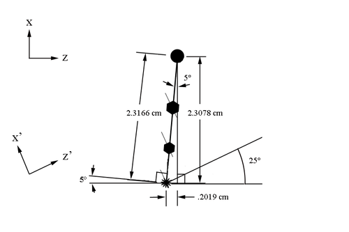
Using the distance from the first guard wire to the first sense wire and the angle found previously,
The starting position for sense wires with respect to the first guard wire at midplane, can be found to be at:
With respect to the target, this location becomes
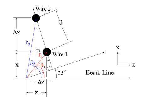
Since the separation between adjacent sense wires is uniform and at a set angle of 25 degrees with respect to the beam line, we can use this fact to determine the angle theta each wire makes when measured from the vertex.
The new x and z coordinates for wire 2 can be found using the change in the components
This can be extended to any point along the same wire plane, starting from the coordinates for wire 1 minus the difference in position to the next wire crossing on the plane.
With this new starting point, a function dependant on the wire number can be derived
The angle theta that the wire makes with the vertex is given by
For the values found earlier for the starting position:
