Difference between revisions of "HM 2014"
| Line 10: | Line 10: | ||
What may forbid the GEM capacitor to reach the equilibrium? | What may forbid the GEM capacitor to reach the equilibrium? | ||
| − | + | # The circuit board voltage fluctuations. | |
| − | |||
=9/18/14= | =9/18/14= | ||
Revision as of 19:49, 20 September 2014
09/20/14
The figure below shows the change in the signal as the GEM capacitor charges, at a specific fixed voltage it reaches saturation (equilibrium),
If the capacitor does not reach equilibrium, the signal of the detector is expected to change with time.
What may forbid the GEM capacitor to reach the equilibrium?
- The circuit board voltage fluctuations.
9/18/14
Determine best Cathode HV that produces the largest separation of the source ON/OFF signal.
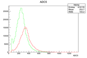
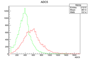
The detector results are not reproducible, as the voltage is at 3.4 kV, the QDC spectrum is different as the source on; so QDC can not distinguish if the source is on or when it is off the detector.
Something is wrong!!!!
We never have a reproducibility problem before using the QDC until I start using V1495, Can we borrow the older module just to test the reproducibility is still a problem.
It is very unlikely that it is the v1495.  The V1495 only tells the DAQ to read out a module.
You can test the DAQ by injecting a pulse with a known charge and look for it in the QDC spectrum.
It is VERY important to have scope pictures showing the difference between source ON/OFF.
Then you use scalers to check that your trigger pulse is able to see a difference between source ON/OFF
Then you do the DAQ measurements.
If you don't follow the above proceedure then you will be building a pyramid on quicksand.
The same case when the cathode voltage increased to 3.6 kV.
Then perform a set of measurements (shutter open/closed and source ON/OFF) to establish reproduceability. Make sure you record the scaler count rates.
9/17/14
Measure the charge for several values of the Cathode HV keeping the GEM preamplifier voltage and gas flow rate constant.
- CATH 3.2 KV
- CATH 3.1 KV
All the runs have the same duration 20 min.
- CATH 3.4 KV
Try to take scope picture to show difference between source on and off signal that are being measured by the QDC.
9/16/14
- Condition of above results
Shutter is Open
Red is Cf-252 source ON Run 7724
Green is Cf-252 source OFF run 7726
HV_GEM= -2930 Volts HV_Cathode=-3400 Volts
Gas Flow rate = 0.1 ft^3/hr
- Goal
- Can the Cf-252 source ON signal be changed?
Change the Cathode voltage to try and turn off the signal when the source is on.
- Result
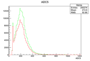
Yes, when the cathode voltage is decreased to -3100V, QDC histogram does not show any difference in the collected charge as the shutter is open with the source on it, and when the shutter is open without the source.
The figure below shows the change in the QDC spectrum when the cathode voltage is -3.2 kV.


