Difference between revisions of "PositronTargetWorkByChrissJackson"
(→ports) |
(→ports) |
||
| Line 65: | Line 65: | ||
|- | |- | ||
| − | | cooling lines || 2 || [ http://www.mdcvacuum.com/DisplayPart.aspx?d=MDC&p=611005 Cooling Hoses] || deleraved | + | | cooling lines || 2 || [http://www.mdcvacuum.com/DisplayPart.aspx?d=MDC&p=611005 Cooling Hoses] || deleraved |
|- | |- | ||
| IR optical window || 1 || [http://www.mdcvacuum.com/DisplayPart.aspx?d=MDC&p=9712007 Optical Window] || delevared | | IR optical window || 1 || [http://www.mdcvacuum.com/DisplayPart.aspx?d=MDC&p=9712007 Optical Window] || delevared | ||
Revision as of 17:48, 15 May 2012
- Chriss Jackson's Positron Target development logbook
- Goal
- Construct a Tungsten target and vacuum enclosure to be used for generating positrons using an incident electron beam.
Geometry
Tungsten Disks
- Dimensions are in cm
http://www.alibaba.com/product-gs/346924116/Tungsten_Disk_With_Screw.html
http://www.zlxtech.com.cn/products.asp?productcode=7401000404
http://www.cleveland-tungsten.com/
If the motor has a radius of 2.5" and I want to shield the motor from the beam using 2" of Pb and the beam is about 1" in diameter then I want a Tungsten disk that is
5.21" in radius = 13.25 cm in radius ~ 30 cm in diameter
Target Chamber design
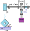
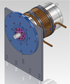
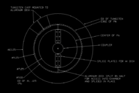
Latest Design From empire and Sadiq's measurement of the available space
 |
 |

| |
| Target motor Design | Available beam line space | Motor axle coupling to rotary union | Hub and spline to attache targets |
Dimensions for the target chamber box. Measurements in inches. updated 11 May 2012. Holes for tubing still missing, need to measure.
 |
 |
 |

|
| Bottom view | Front View | Left View | Isometric View |
ports
- 2 beam line ports, (
- 2 coollant ports
- 1 electrical port
- Ion pump port
| Parts | Quantity | Link | Delevary status |
| 10 - pin wiring feedthrough | 1 | Feedthrough | |
| cooling lines | 2 | Cooling Hoses | deleraved |
| IR optical window | 1 | Optical Window | delevared |
The resolution in the above image makes it too dificult to read the numbers. See if you can upload a PDF version.
1.) Lid with a lip that bolts on.
2.) bolt pattern on the bottom for the motor mounts
3.) find cooling lines for inside the box
4.) Find elbows for the rotary unions.
. . . . 100.) Design a target mounting system
Equipment
Motor
Controller
Vacuum Chamber
Feedthroughs
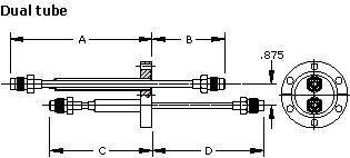
A: 5.88 B: 3.00 C: 4.25 D: 4.63
http://www.mdcvacuum.com/DisplayPart.aspx?d=MDC&p=611005

