Difference between revisions of "Rotating Tungsten Target System"
Jump to navigation
Jump to search
| Line 28: | Line 28: | ||
[[file:STR8.png | 300 px]] | [[file:STR8.png | 300 px]] | ||
| + | |||
| + | == Power Supply== | ||
| + | |||
| + | [[File:Rotating_Tar_PS.pdf]] | ||
== Document == | == Document == | ||
Revision as of 06:25, 29 March 2012
Parts
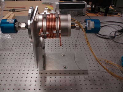
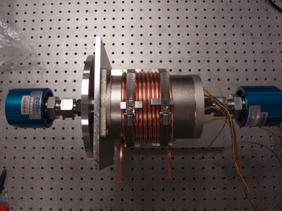
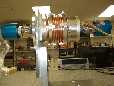
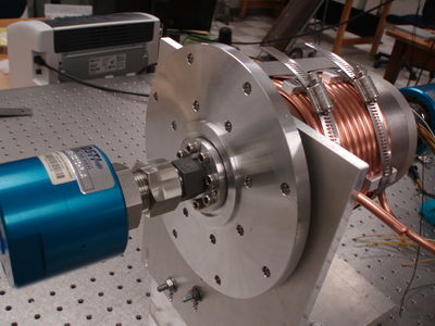
[More Images ]
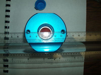
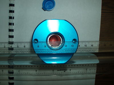
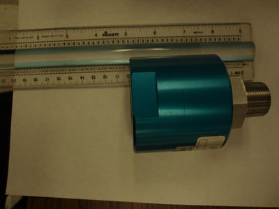
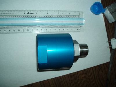
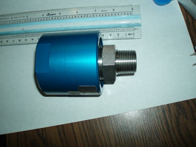
Rotating Union
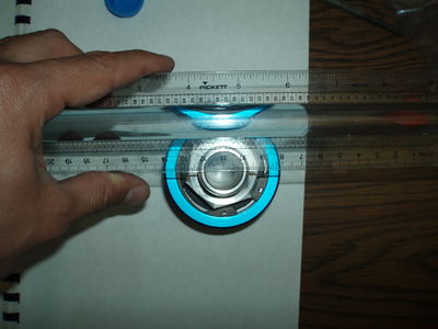
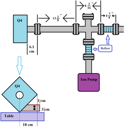
Positron Target Box
The pipe that go through quads has inner diameter: 47.38 * mm
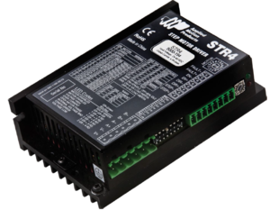
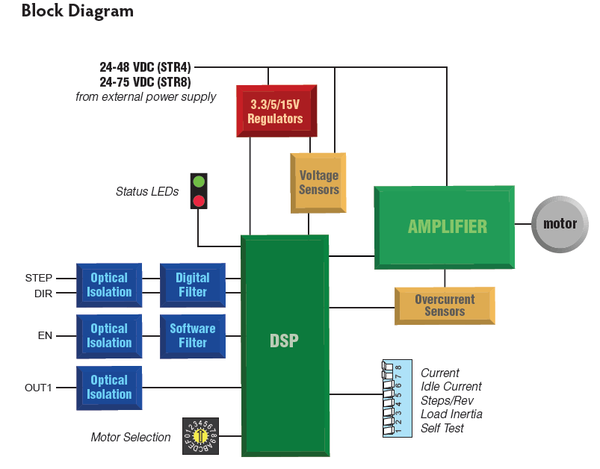
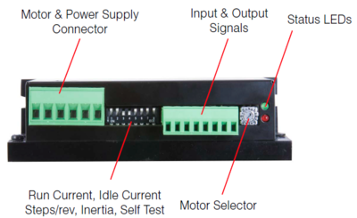
STR8 - Step Motor Drives
Applied Motion Products motor control.
Power Supply
Document
STR8 Manuals:
Media:STR_Quick_Setup_Guide.pdf
Datasheet:
Media:STR_Brochure_925-0002_RevC.pdf
2D Drawing:
Speed-Torque Curves:
Features
Operates from a 24 to 75 volt DC power supply
Running current up to 7.8 amps per phase
Other Parts needed
1) a 24 to 75 volt DC power supply
2) a source of step signals, such as a PLC or motion controller.
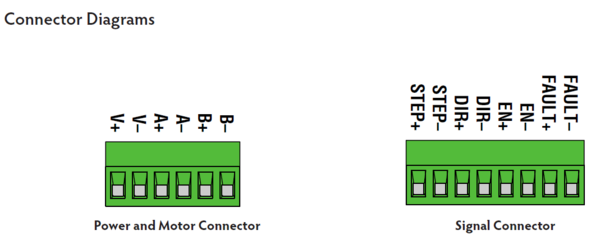
Wire Connection
Wiring the Motor
Connect the drive to the motor. Four lead motors can be connected in only one way, as shown in Figure 1. We recommend that eight lead motors be connected in parallel, as shown in Figure 2. If using a non-Applied Motion Products motor, please refer to your motor specs for wiring information.
