Difference between revisions of "Turning on HRRL"
Jump to navigation
Jump to search
| (18 intermediate revisions by the same user not shown) | |||
| Line 3: | Line 3: | ||
Chiller room | Chiller room | ||
| − | + | [[File:Turning_on_HRRL_chiller_room_1.jpg | 400 px]] [[File:Turning_on_HRRL_chiller_room_2.jpg | 400 px]] | |
| + | |||
| + | Pump switches: | ||
off [[File:Turning_on_HRRL_cooling_main_system_1.jpg | 400 px]] on [[File:Turning_on_HRRL_cooling_main_system_2.jpg | 400 px]] | off [[File:Turning_on_HRRL_cooling_main_system_1.jpg | 400 px]] on [[File:Turning_on_HRRL_cooling_main_system_2.jpg | 400 px]] | ||
| Line 10: | Line 12: | ||
= Turn on ISA water skid system = | = Turn on ISA water skid system = | ||
| + | |||
| + | [[File:Turning_on_HRRL_ISA_water_skid_system_1.jpg | 400 px]] [[File:Turning_on_HRRL_ISA_water_skid_system_2.jpg | 400 px]] | ||
| + | |||
| + | [[File:Turning_on_HRRL_ISA_water_skid_system_3.jpg | 400 px]] [[File:Turning_on_HRRL_ISA_water_skid_system_4.jpg | 400 px]] | ||
| + | |||
off [[File:Turning_on_HRRL_cooling_main_system_3.jpg | 400 px]] on [[File:Turning_on_HRRL_cooling_main_system_4.jpg | 400 px]] | off [[File:Turning_on_HRRL_cooling_main_system_3.jpg | 400 px]] on [[File:Turning_on_HRRL_cooling_main_system_4.jpg | 400 px]] | ||
| + | |||
Turn on breaker and then press start. | Turn on breaker and then press start. | ||
| Line 19: | Line 27: | ||
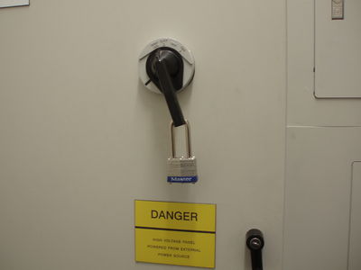
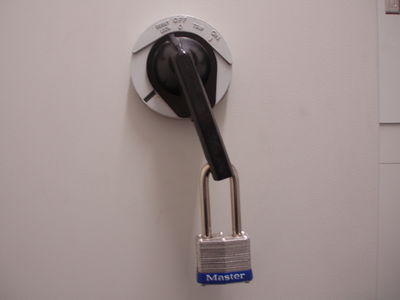
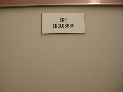
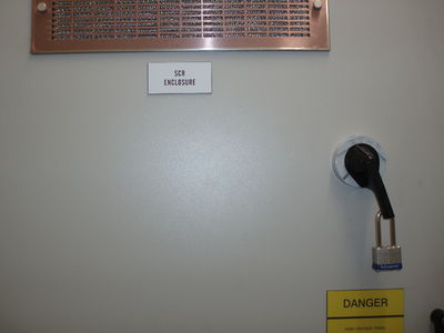
Unlock padlock on SCR Enclosure on Moculator and turn switch to on. (This turns on 480 V AC for HVPS) | Unlock padlock on SCR Enclosure on Moculator and turn switch to on. (This turns on 480 V AC for HVPS) | ||
| + | |||
| + | [[File:Turning_on_HRRL_modulator_1.jpg | 400 px]] | ||
| + | [[File:Turning_on_HRRL_modulator_2.jpg | 400 px]] | ||
| + | |||
| + | [[File:Turning_on_HRRL_modulator_3.jpg | 400 px]] | ||
| + | [[File:Turning_on_HRRL_modulator_4.jpg | 400 px]] | ||
| + | |||
| + | [[File:Turning_on_HRRL_modulator_5.jpg | 400 px]] | ||
| + | [[File:Turning_on_HRRL_modulator_6.jpg | 400 px]] | ||
| + | |||
| + | [[File:Turning_on_HRRL_modulator_7.jpg | 400 px]] | ||
| + | [[File:Turning_on_HRRL_modulator_8.jpg | 400 px]] | ||
= Turn on filament= | = Turn on filament= | ||
| Line 29: | Line 49: | ||
[[File:Turning_on_HRRL_touchscreen_at_control_rack.jpg | 400 px]] | [[File:Turning_on_HRRL_touchscreen_at_control_rack.jpg | 400 px]] | ||
| + | [[File:Turning_on_HRRL_touchscreen_at_control_rack_2.jpg | 400 px]] | ||
| Line 39: | Line 60: | ||
= Turn on magnet power supplies = | = Turn on magnet power supplies = | ||
| − | [[File:Turning_on_HRRL_turn_on_magnet_power_supplies_1.jpg | | + | [[File:Turning_on_HRRL_turn_on_magnet_power_supplies_1.jpg | 300 px ]] |
[[File:Turning_on_HRRL_turn_on_magnet_power_supplies_2.jpg | 400 px ]] | [[File:Turning_on_HRRL_turn_on_magnet_power_supplies_2.jpg | 400 px ]] | ||
| + | |||
| + | [[File:Turning_on_HRRL_turn_on_magnet_power_supplies_3.jpg | 300 px ]] | ||
| + | [[File:Turning_on_HRRL_turn_on_magnet_power_supplies_4.jpg | 300 px ]] | ||
| + | [[File:Turning_on_HRRL_turn_on_magnet_power_supplies_5.jpg | 300 px ]] | ||
| + | |||
| + | [[File:Turning_on_HRRL_turn_on_magnet_power_supplies_6.jpg | 350 px ]] | ||
| + | [[File:Turning_on_HRRL_turn_on_magnet_power_supplies_7.jpg | 350 px ]] | ||
| + | [[File:Turning_on_HRRL_turn_on_magnet_power_supplies_8.jpg | 350 px ]] | ||
= Check if the modulator is on = | = Check if the modulator is on = | ||
| Line 51: | Line 80: | ||
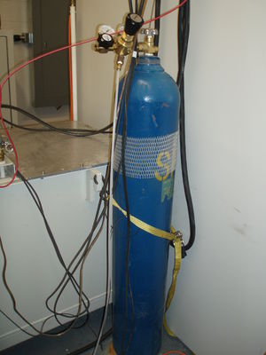
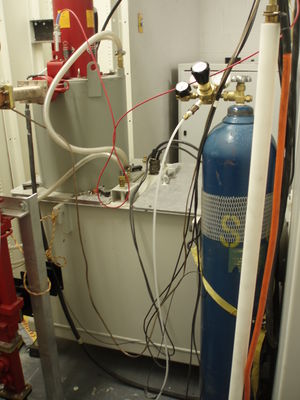
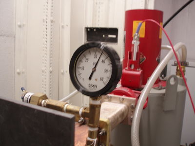
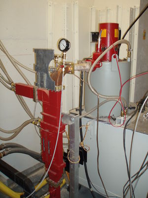
Gas tank: | Gas tank: | ||
[[File:Turning_on_HRRL_fill_wave_guide_with_SF6_gass_Tank.jpg | 400 px ]] | [[File:Turning_on_HRRL_fill_wave_guide_with_SF6_gass_Tank.jpg | 400 px ]] | ||
| + | [[File:Turning_on_HRRL_fill_wave_guide_with_SF6_gass_Tank_2.jpg | 300 px ]] | ||
| + | [[File:Turning_on_HRRL_fill_wave_guide_with_SF6_gass_Tank_3.jpg | 300 px ]] | ||
| + | |||
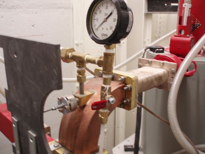
valve off position: | valve off position: | ||
[[File:Turning_on_HRRL_fill_wave_guide_with_SF6_gass_swtich_valve_off.jpg | 400 px ]] | [[File:Turning_on_HRRL_fill_wave_guide_with_SF6_gass_swtich_valve_off.jpg | 400 px ]] | ||
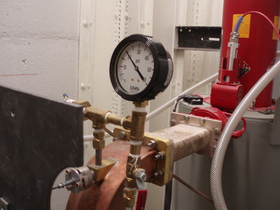
| − | valve | + | valve on position: |
[[File:Turning_on_HRRL_fill_wave_guide_with_SF6_gass_swtich_valve_on.jpg | 400 px ]] | [[File:Turning_on_HRRL_fill_wave_guide_with_SF6_gass_swtich_valve_on.jpg | 400 px ]] | ||
Fill up to 35 lbs: | Fill up to 35 lbs: | ||
[[File:Turning_on_HRRL_fill_wave_guide_with_SF6_gass_swtich_fill_upto_35lbs.jpg | 400 px ]] | [[File:Turning_on_HRRL_fill_wave_guide_with_SF6_gass_swtich_fill_upto_35lbs.jpg | 400 px ]] | ||
| + | |||
| + | |||
| + | [[File:Turning_on_HRRL_fill_wave_guide_with_SF6_gass_swtich_valve_1.jpg | 300 px ]] | ||
| + | [[File:Turning_on_HRRL_fill_wave_guide_with_SF6_gass_swtich_valve_2.jpg | 300 px ]] | ||
| + | [[File:Turning_on_HRRL_fill_wave_guide_with_SF6_gass_swtich_valve_3.jpg | 300 px ]] | ||
= Turn switch to enable building interlcok system= | = Turn switch to enable building interlcok system= | ||
Latest revision as of 03:52, 20 February 2011
Turn on water pump for cooling system
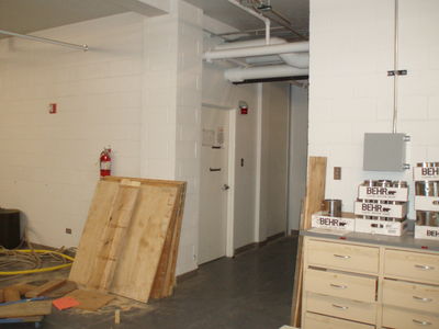
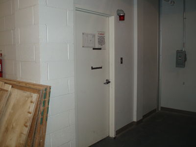
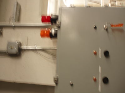
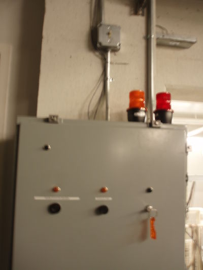
Chiller room
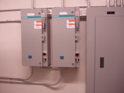
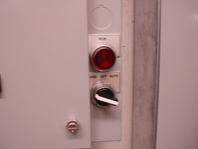
Pump switches:
There are two pumps, use them alternatively when run multiple days.
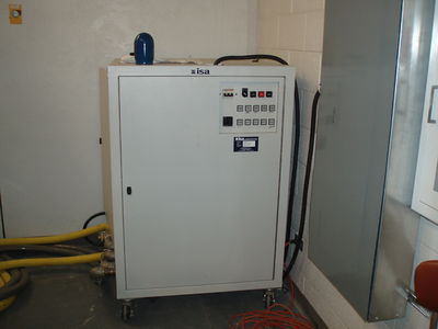
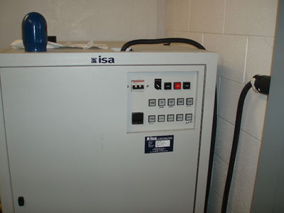
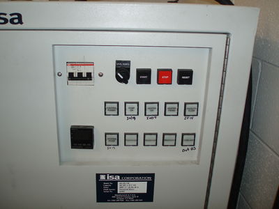
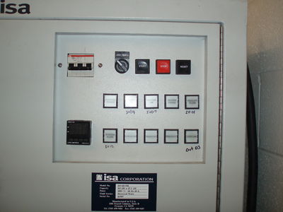
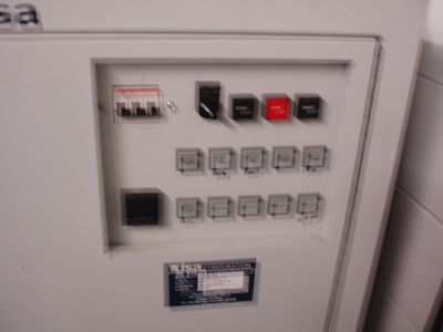
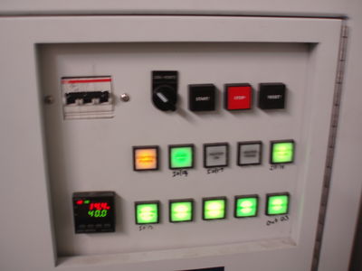
Turn on ISA water skid system
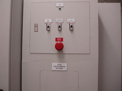
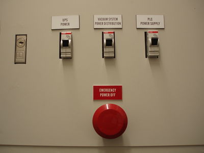
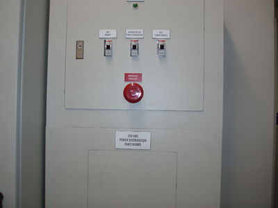
Turn on breaker and then press start.
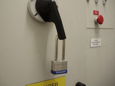
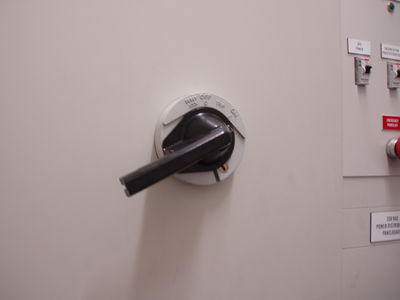
Turn on Modulator
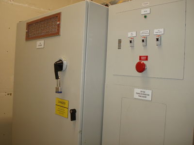
Unlock padlock on SCR Enclosure on Moculator and turn switch to on. (This turns on 480 V AC for HVPS)
Turn on filament
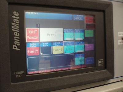
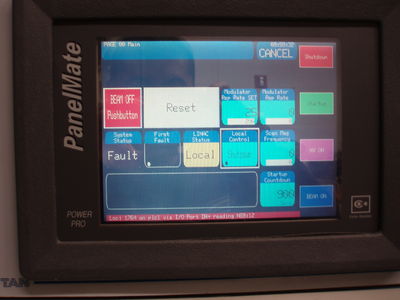
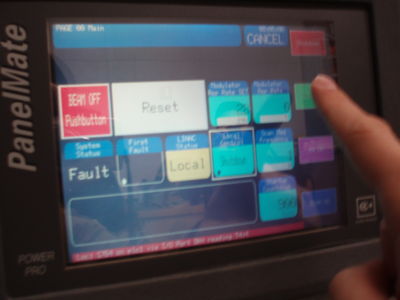
Press Startup on PanelMate touchscreen locate at control rack
Touchscreen at control rack:
Press "startup":
Wait for 900 s count down.
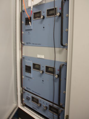
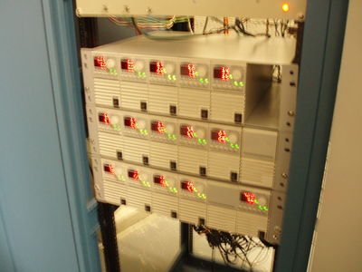
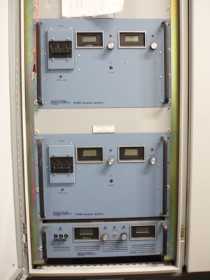
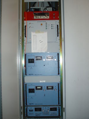
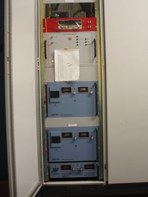
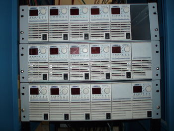
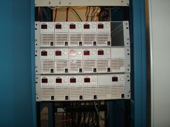
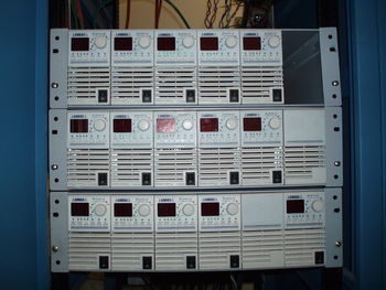
Turn on magnet power supplies
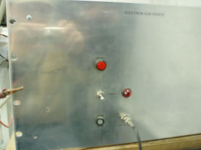
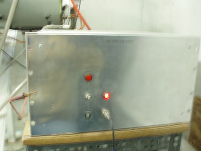
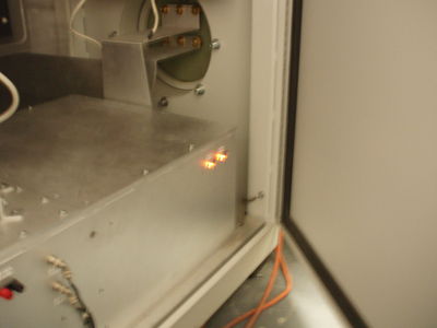
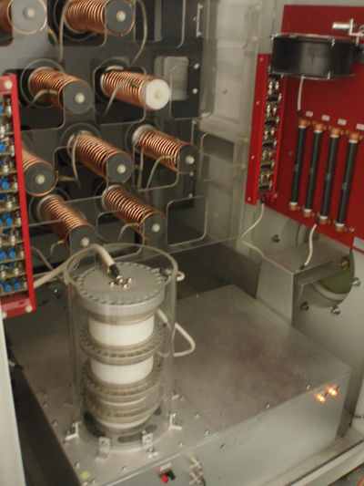
Check if the modulator is on
if the two lights at the corner of the box is on, then modulator is on.
