Difference between revisions of "DeltaDoverD Progress"
(→9/5/08) |
(→9/5/08) |
||
| Line 37: | Line 37: | ||
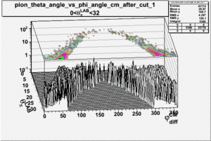
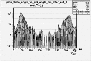
[[Image:pion_theta_vs_phi_angle_cm_Theta_pion_lab_0_32_3D.gif|300px]][[Image:phi_angle_cm_Theta_pion_lab_0_32_3D.gif|300px]]<br> | [[Image:pion_theta_vs_phi_angle_cm_Theta_pion_lab_0_32_3D.gif|300px]][[Image:phi_angle_cm_Theta_pion_lab_0_32_3D.gif|300px]]<br> | ||
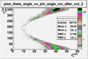
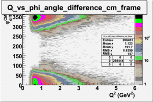
| − | + | <math>Q^2</math>_vs_<math>\phi_{diff}^{CM}</math> plot shows that the <math>Q^2</math> cut should not make much difference on <math>\phi_{diff}^{CM}</math> plot. The cut around <math>1 GeV^2 < Q^2< 2 GeV^2</math> should reduce the number of pions around 0 and 360 of phi angle.<br> | |
[[Image:Q_sqrd_vs_phi_angle_in_cm_frame_after_cuts_all_Q.gif|300px]]<br> | [[Image:Q_sqrd_vs_phi_angle_in_cm_frame_after_cuts_all_Q.gif|300px]]<br> | ||
Revision as of 22:17, 18 September 2008
9/5/08
1.) SIDIS Analysis
a.) Cross-Section comparison
Figure out the definition of cross-section being used in the data
i.) Calculate absolute cross section for Cos Thet_pi = 0.5, 1 < Q^2 < 4 GeV^2 , W = 1.45 +/- 0.2 GeV
ii.) Plot -vs- when = -0.3 also plot -vs-
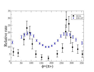
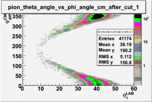
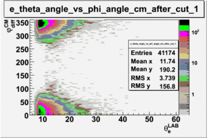
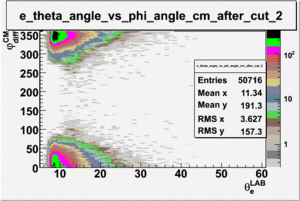
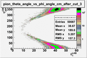
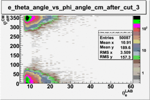
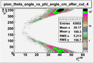
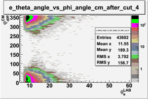
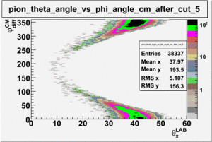
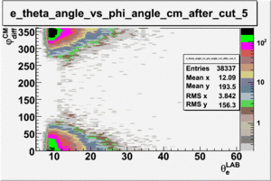
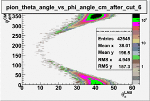
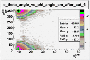
As one can see from histograms of the pion_theta_angle_vs_phi_angle_in_CM_Frame and the electron_theta_angle_vs_phi_angle_in_CM_Frame, the pion and electron acceptance in the region of is nearly zero(significantly low).
_vs_ plot shows that the cut should not make much difference on plot. The cut around should reduce the number of pions around 0 and 360 of phi angle.
make plots for .
2.) Detector Construction
4 chambers are built.
TGEM:
Foils have been mounted on the TGEM comparison chamber. Both charge collectors are mounted on the TGEM test detectors. One TGEM test detector has the Thick PC board GEM foils which need much higher HV than the regular GEM foils. The second TGEM test chamber has 3 GEM foils from CERN.
Need a min of 32 1 Meg Ohm resistors to complete the output termination connectors. Need 32 more termination connectors made from 16 wires.
Need to grind down 16, M3 bolts for mounting the GEM foils and TGEM PCboards.
Need 24 washers for GEM foils. Check mounting of the TGEM boards. Look up spacing and HV for the TGEM boards[1], Media:01352098.pdf .
Need to etch 2 cathodes for the TGEm boards.
Qweak:
a.) Need to do final outer footprint machining so there is no interference with the Electron profile of the other octant.
b.) Need to machining back of the chamber for the Charge collector
c.) Need to machine thick frames for the cathode and maybe GEM foils.
d.) Apply electrical insulation to HV distribution boards
e.) Need to mount GEM foils on the Qweak chambers.
3.) SIS3610 I/O software
Objectives: a.) The first step will be to read 16 of the I/O input channel into a CODA data file.
b.) Display the 16 input channels on a GUI. Unfortunately, only 2 of the 16 will be used to read in the GEM output. The GEM output will transfer 128 hit/no hit signals to a single I/O channel in a serial fashion. The data from one I/O channel needs to be decoded according to the data structure described in Figure 8 and 9 of the VFAT manual.
c.) The final task will be to write a multiple trigger function so the I/O can be triggered by several different interrupt trigger signals and label those trigger signals.
Tasks:
Inject a signal into the I/O board input connector and use a Read function from the ROC to determine if the signal is high or low.
