Difference between revisions of "CHIPS Run May-2008"
| Line 158: | Line 158: | ||
|[http://en.wikipedia.org/wiki/Tantalum Tantalum] Foil|| 6 mm thick 20 mm x 20 mm area | |[http://en.wikipedia.org/wiki/Tantalum Tantalum] Foil|| 6 mm thick 20 mm x 20 mm area | ||
|- | |- | ||
| − | |[http://en.wikipedia.org/wiki/Tungsten Tungsten] || 2 mm thick 20 mm x 20 mm area | + | |[http://en.wikipedia.org/wiki/Tungsten Tungsten] Foil|| 2 mm thick 20 mm x 20 mm area |
|- | |- | ||
| − | |Phosphorus Flag|| 1 mil aluminum backing | + | |[http://en.wikipedia.org/wiki/Phosphorus Phosphorus] Flag|| 1 mil aluminum backing |
|- | |- | ||
|HpGe Crystal|| | |HpGe Crystal|| | ||
Revision as of 12:49, 17 June 2008
Goals
- Determine smallest beam spot size using JLAB flags at the zero degre port and after the 90 degree bend on the 25 MeV machine current beam line
- Install FC and measure its performance (smallest controllable current attainable)
- Measure background rates for positron production
Run Plan
May 27,2008
Spend Day tuning with the following goals
1.) Minimize beam spot size on zero port and document with image grabber. 1 mm diameter beam spot size is the goal.
2.) Check spot size on flag after 90 degree bend. Tungsten target out
3.) Try to re-tune the beam spot after the 90 degree bend to a 1mm diameter
4.) Optimize transmission to FC.
5.) loop over steps 1-4 above to find tune which delivers highest transmission and smallest beam spot size.
6.) Measure beam spot size over the lowest to highest range possible beam current range with the phosphorus screens.
May 28, 2008
1.) turn on NaI and HpGe detectors.
HpGE: +4800V, use 223/U cable
Output 1: 223A5 output 2: 223A6
NaI: 223A5: 1310V
FC flange : on 2223A23 FC: output on :223A24
2.) Tune beam to deliver 3 MeV electrons into experimental cell.
3.) change beam energy back to 10 MeV using magnet settings from yesterday which minimize spot on zero degree port.
4.) use magnet settings from 3 MeV beam tune on magnets after the tungsten foils, reverse polarity of last dipole to sweep postirons into hall.
5.) minimize background. Add lead shielding around Germanium target and NaI so Tantalum In/out ratio is maxed at the 0.511 keV gamma energy bin.
6.) measure the contributions from positrons and photons.
  a.) Use the last Phosphorus flag to stop positrons
  b.) With above flag in, add a permanent magnet in front of the flag to check that positrons have been stopped.
  c.) remove Tantalum target to measure remaining background
May 29, 2008
Measure 0.511 keV gammas as a function of beam current
May 30, 2008
1.) Tune 4 MeV electron beam to experimental Cell (Tungsten and Tantalum target out).
a.) tune a small circular beam spot onto the 90 degree Phosphorus screen.
b.) Change last 3 quads to maximize transmission to the experimental cell
 by maximizing the FC to FC collar ratio.
c.) record the values of the last 3 quads.  We will keep the quad between the
tungsten target and the last dipole at the same value and polarity but switch the
polarity of the last two quads when running positrons.
2.) Tune 10 MeV electrons to the zero line Phosphorus screen to minimize spot size.
3.) Use the first dipole to sent 10 MeV electrons to the Tungsten target. Insert Tungsten Target.
4.) Set last dipole to deliver 3 MeV positrons to the experimental cell.
5.)Measure the 511 keV gamma spectrum using the HpGe and NaI detectors as a function of the last dipole current/energy with the last two quads turned off.
6.)Set the last dipole to deliver the max positron yield when the last two quads are off.
7.) Send the operators the HpGe signal and have them try to Max the pulse rate by adjusting the last two quads with a polarity opposite to their setting for electrons.
8.) Measure the Positron yield as a function of beam current.
LogBook
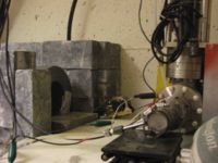
apparatus
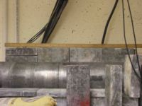
8" lead shielding wall
Solvable Problems:
1.) JLAB would like beam spot of 1 mm. Measured 8 mm after thick window. Doug reported measuring 3 mm without thick window.
2.) Lowering beam current: 10^8 electrons/pulse desired to produce 1 positron per pulse. Perhaps slits can solve the above problems and then localized lead shielding to reduce backgrounds.
3.) Beam position monitoring. Flags from JLab have arrived Brett will look into installing.
May run on IAC schedule for 27,28,29,30
need cameras for the flags.
Next steps after Feb run:
1.) Optimize develop beam line design. Serkan needs more input about the IAC beam properties.
2.)Proposal is to measure beam properties with flags and FCUP during May 27-30 run. (parts to install beam line flags is critical path defining the run start date).
   a.)Measure beam shape at zero degree port and after 90 degree bend
   b.) install FCUP (2 3/4 flange)
   c.) measure background rates

      i.) one flag has positron converter in experimental cell.
      ii.) dipole on experimental cell side
      iii.) photon veto using scintillators
3.) Future beam line
 a.) perhaps move converter target between dipole
 b.) 50 ns beam pulse may give you +/- 2 MeV spread
Targets
1.) Tantalum foil 2.0 mm (99.5% metals basis) lot # D11S010, stock # 10357
2.) Tungsten foil, 1.0 mm thick, 99.5% metals basis, LOT # H23R015, stock #13981
Phosphorus targets:
3.5 cm center to center distance between mount bolts. IAC phosphorus is 0.010 inches of phosphorus mounted onto 0.025 thick Aluminum
Apparatus Sketch
Simple sketch of Positron Beam line with detectors
| Item | Description |
| Tantalum Foil | 6 mm thick 20 mm x 20 mm area |
| Tungsten Foil | 2 mm thick 20 mm x 20 mm area |
| Phosphorus Flag | 1 mil aluminum backing |
| HpGe Crystal | |
| NaI detector |


