VFAT powered on and responding to I2C
Jump to navigation
Jump to search
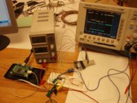
The image below shows the apparatus used to look at I2C commands
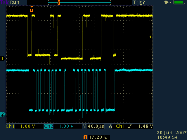
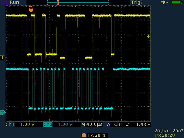
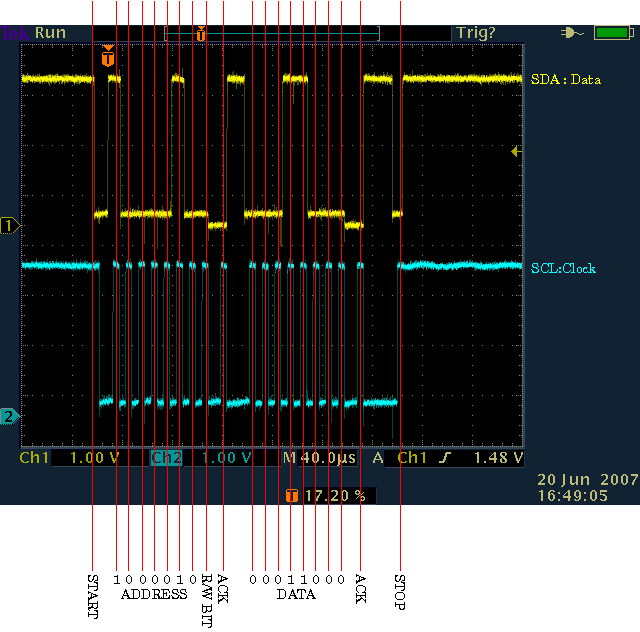
These are pictures of I2C operations with the VFAT board. In this example the VFAT is set to addresses 0x40 thru 0x4F.
- START: Master transistions SDA high to low while SCL is high, asserting control of the bus.
- ADDRESS: 7-bit address of the slave device, 0x48 or 0b1000010 (IPreampIn) in this case.
- R/W BIT: Set to 1 for a read operation, 0 for a write operation, 0 (write) in this case
- ACK: Slave device pulls down SDA (notice the lower low level from the slave) and the master sends another pulse on SCL to acknowledge the last byte.
- DATA: 8-bit value, most significant bit first. Slave and master release SCL, allowing it to go high as they transfer or are ready to receive the next bit. In this case the data is 0x18 or 00011000.
- ACK: Another ACK to acknowledge the second byte.
- STOP: Master transitions SDA low to high while SCL is high, releasing control of the bus.

The IPreampIn byte that was just set is read. The address is 0x42 and the value is 0x18.

One byte of the VFAT ChipID is read from address 0x48. The value is 0xF3.

