Difference between revisions of "VFAT powered on and responding to I2C"
Jump to navigation
Jump to search
| Line 1: | Line 1: | ||
| − | + | These are pictures of i2c operations with the VFAT board. In this example the VFAT is set to addresses 0x40 o 0x4F. | |
| − | |||
| − | |||
[[Image:i2c_scope_read_48.png]] | [[Image:i2c_scope_read_48.png]] | ||
| + | One byte of the VFAT ChipID is read from address 0x48. The result is F3. | ||
| − | + | [[Image:i2c_scope_write_42.png]] | |
| − | The | + | The IPreampIn byte at address 0x42 is set to 0x18. |
| − | The | + | [[Image:i2c_scope_read_42.png]] |
| + | The IPreampIn byte that was just set is read. The address is 0x42 and the data is 0x18. | ||
Revision as of 21:36, 20 June 2007
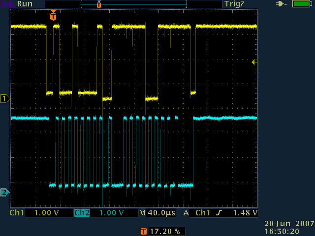
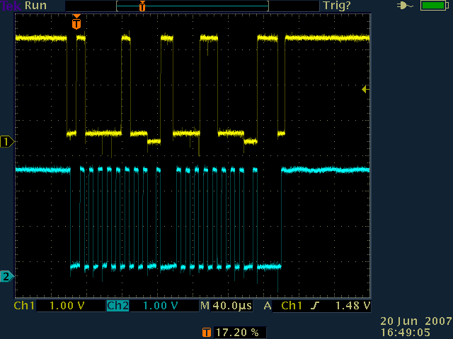
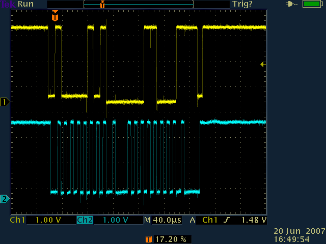
These are pictures of i2c operations with the VFAT board. In this example the VFAT is set to addresses 0x40 o 0x4F.
 One byte of the VFAT ChipID is read from address 0x48. The result is F3.
 The IPreampIn byte at address 0x42 is set to 0x18.
 The IPreampIn byte that was just set is read. The address is 0x42 and the data is 0x18.