Difference between revisions of "Uniform distribution in Energy and Theta LUND files"
| (113 intermediate revisions by the same user not shown) | |||
| Line 1: | Line 1: | ||
| − | + | <center><math>\underline{\textbf{Navigation}}</math> | |
| − | + | [[Preparing_Drift_Chamber_Efficiency_Tests|<math>\vartriangleleft </math>]] | |
| + | [[VanWasshenova_Thesis#Preparing_Drift_Chamber_Efficiency_Tests|<math>\triangle </math>]] | ||
| + | [[1000_Events_per_degree_in_the_range_5_to_40_degrees_for_Lab_Frame|<math>\vartriangleright </math>]] | ||
| − | + | </center> | |
| − | |||
| − | |||
| − | [[File: | + | =4.1 Uniform Distribution in Energy and Theta LUND files= |
| + | [[File:LUND_Spread.C|Creating uniform LUND files]] | ||
| + | To ensure that all the electrons simulated in GEMC are Moller electrons, electrons are first creating in the center of mass frame after scattering has occured. In this frame, the Moller differential cross section is well defined, and can be used to ensure that all particles to be simulated in other frames of reference will be Moller electrons. Due to the fact that GEMC simulations will utilize particle momentum in the lab frame, this imlies the LUND files must contain lab frame information. The transformation from CM to lab frame can be done using Lorentz boosts. In addition, all the data given is for 11GeV electrons that have not yet had the chance to interact with the target material. This implies that all electrons have the same incident energy in the lab, and as such have a constant value in the CM frame. | ||
| − | |||
| − | + | In the lab frame there are 2 degrees of freedom, i.e. <math>P_{\theta}</math> and <math>P_{\phi}</math> . The number of degrees of freedom can be reduced to 1 degrees of freedom in the center of mass frame of reference since the Moller differential cross section does not rely on <math>\phi</math> and all energies are considered equal in the CM frame. The simplicity of the center of mass frame for Moller electrons is that the interacting particles have equal energies and equal but opposite momentum vectors. In such a system where these conditions must be met, the directions of the momentum vectors must be opposite, which reduces the degrees of freedom to one direction. Since the Moller differential cross-section only relies on <math>\theta</math> in all frames it implies for a given angle <math>\theta</math> we should find the same results for any given angle <math>\phi</math>. | |
| − | |||
| + | To ensure that we can produce the Moller differential cross section in the center of mass frame we start with a uniform isotropic distribution of Moller electrons with respect to the scattering angle theta. From this distribution, each particle can be applied an appropriate weight that will result in the differential cross section being reproduced. | ||
| − | <center> | + | <center><gallery widths=500px heights=400px> |
| + | File:MolThetaCM_spread.png|'''Figure 4.1.1:''' An Isotropic CM frame distribution of final scattering angle theta for Moller electrons. 90-180 degrees in the center of mass frame, with a spacing of .0001 degree increments. | ||
| + | File:MolMomCM_spread.png|'''Figure 4.1.2:''' An CM frame distribution for an isotropic distribution in final scattering angle theta for Moller electrons. All Moller electrons in the center of mass frame have the same energy, and equal but opposite momentum vectors. | ||
| + | </gallery></center> | ||
| − | |||
| − | |||
| − | |||
| − | In the | + | The LUND file is created by creating an isotropic distribution of electrons within the Moller center of mass frame of reference after scattering. These particles are uniformly distributed through the angle theta with respect to the beam line in the range 90-180 in the center of mass frame. This is initially done at a set angle phi (0 degrees) with respect to the perpendicular components with respect to the beam line. In the CM frame, the spacing of the angle theta bins are 0.0001 degrees wide. A Lorenz contraction occurs for a particle's momentum component that is parallel to the beam line. As the angle of the particle approaches a direction perpendicular to the beam line, the Lorentz contraction decreases. As a result, a uniform angular distribution in the Lab frame will not be uniform in the CM frame. |
| − | + | [[File: Mankowski_Diagram.png |thumb | border | center |600 px |alt=Mankowski Diagram demonstrating Lorentz contraction|'''Figure 2:''' A Mankowski diagram demonstrating the Lorentz contraction increasing as the z component approaches the speed of light. Taking the perpendicular axis as the lab frame, the spacing between the arbitary measurements is equal when viewed from within the specific frame, but unequal as shown by the dots viewed from the lab frame.]] | |
| + | This implies that the number of events that occur in the lab frame of reference near the beam line is larger than the number as it approaches a perpendicular direction. To understand the "density" of the number of events per bins in the lab frame, a study of 1000 events in the center of mass frame per 0.01 degree in the lab frame is investigated. A weighting factor, used to reproduce the Moller cross section, appears in the LUND file but not the GEMC evio output file thereby requiring both the LUND and evio files to be read simultaneously. | ||
| − | |||
| − | |||
| − | |||
| − | |||
| + | ---- | ||
| − | |||
| − | |||
| − | + | <center><math>\underline{\textbf{Navigation}}</math> | |
| − | < | + | [[Preparing_Drift_Chamber_Efficiency_Tests|<math>\vartriangleleft </math>]] |
| + | [[VanWasshenova_Thesis#Preparing_Drift_Chamber_Efficiency_Tests|<math>\triangle </math>]] | ||
| + | [[1000_Events_per_degree_in_the_range_5_to_40_degrees_for_Lab_Frame|<math>\vartriangleright </math>]] | ||
| − | + | </center> | |
| − | |||
| − | |||
| − | |||
| − | |||
| − | |||
| − | |||
| − | |||
| − | |||
| − | |||
| − | |||
| − | |||
| − | |||
| − | |||
| − | |||
| − | |||
| − | |||
| − | |||
| − | |||
| − | |||
| − | |||
| − | |||
| − | |||
| − | |||
| − | |||
| − | |||
| − | |||
| − | |||
| − | |||
| − | |||
| − | |||
| − | |||
| − | |||
| − | |||
| − | |||
| − | |||
| − | |||
| − | |||
| − | |||
| − | |||
| − | |||
| − | |||
| − | |||
| − | |||
| − | |||
| − | |||
| − | |||
| − | |||
| − | |||
| − | |||
| − | |||
| − | |||
| − | |||
| − | |||
| − | |||
| − | |||
| − | |||
| − | |||
| − | |||
| − | |||
| − | |||
| − | |||
| − | |||
| − | |||
| − | |||
| − | |||
| − | |||
| − | |||
| − | |||
| − | |||
| − | |||
| − | |||
| − | |||
| − | |||
| − | |||
| − | |||
| − | |||
| − | |||
| − | |||
| − | |||
| − | |||
| − | |||
| − | |||
| − | |||
| − | |||
| − | |||
| − | |||
| − | |||
| − | |||
| − | |||
| − | |||
| − | |||
| − | |||
| − | |||
| − | |||
| − | |||
| − | |||
| − | |||
| − | |||
| − | |||
| − | |||
| − | |||
| − | |||
| − | |||
| − | |||
| − | |||
| − | |||
| − | |||
| − | |||
| − | |||
| − | |||
| − | |||
| − | |||
| − | |||
| − | |||
| − | |||
| − | |||
| − | |||
| − | |||
Latest revision as of 20:44, 15 May 2018
4.1 Uniform Distribution in Energy and Theta LUND files
To ensure that all the electrons simulated in GEMC are Moller electrons, electrons are first creating in the center of mass frame after scattering has occured. In this frame, the Moller differential cross section is well defined, and can be used to ensure that all particles to be simulated in other frames of reference will be Moller electrons. Due to the fact that GEMC simulations will utilize particle momentum in the lab frame, this imlies the LUND files must contain lab frame information. The transformation from CM to lab frame can be done using Lorentz boosts. In addition, all the data given is for 11GeV electrons that have not yet had the chance to interact with the target material. This implies that all electrons have the same incident energy in the lab, and as such have a constant value in the CM frame.
In the lab frame there are 2 degrees of freedom, i.e. and . The number of degrees of freedom can be reduced to 1 degrees of freedom in the center of mass frame of reference since the Moller differential cross section does not rely on and all energies are considered equal in the CM frame. The simplicity of the center of mass frame for Moller electrons is that the interacting particles have equal energies and equal but opposite momentum vectors. In such a system where these conditions must be met, the directions of the momentum vectors must be opposite, which reduces the degrees of freedom to one direction. Since the Moller differential cross-section only relies on in all frames it implies for a given angle we should find the same results for any given angle .
To ensure that we can produce the Moller differential cross section in the center of mass frame we start with a uniform isotropic distribution of Moller electrons with respect to the scattering angle theta. From this distribution, each particle can be applied an appropriate weight that will result in the differential cross section being reproduced.
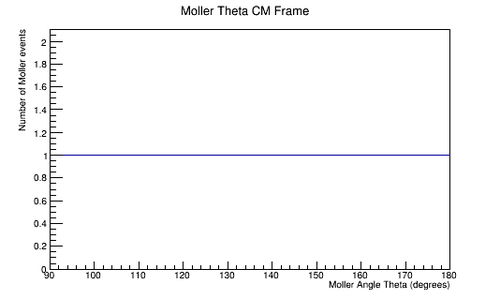
Figure 4.1.1: An Isotropic CM frame distribution of final scattering angle theta for Moller electrons. 90-180 degrees in the center of mass frame, with a spacing of .0001 degree increments.
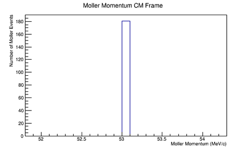
Figure 4.1.2: An CM frame distribution for an isotropic distribution in final scattering angle theta for Moller electrons. All Moller electrons in the center of mass frame have the same energy, and equal but opposite momentum vectors.


The LUND file is created by creating an isotropic distribution of electrons within the Moller center of mass frame of reference after scattering. These particles are uniformly distributed through the angle theta with respect to the beam line in the range 90-180 in the center of mass frame. This is initially done at a set angle phi (0 degrees) with respect to the perpendicular components with respect to the beam line. In the CM frame, the spacing of the angle theta bins are 0.0001 degrees wide. A Lorenz contraction occurs for a particle's momentum component that is parallel to the beam line. As the angle of the particle approaches a direction perpendicular to the beam line, the Lorentz contraction decreases. As a result, a uniform angular distribution in the Lab frame will not be uniform in the CM frame.

This implies that the number of events that occur in the lab frame of reference near the beam line is larger than the number as it approaches a perpendicular direction. To understand the "density" of the number of events per bins in the lab frame, a study of 1000 events in the center of mass frame per 0.01 degree in the lab frame is investigated. A weighting factor, used to reproduce the Moller cross section, appears in the LUND file but not the GEMC evio output file thereby requiring both the LUND and evio files to be read simultaneously.