|
|
| Line 1: |
Line 1: |
| | =9/5/08= | | =9/5/08= |
| | | | |
| − | == SIDIS Analysis==
| |
| − |
| |
| − | a.) Cross-Section comparison
| |
| − |
| |
| − | i.) Calculate absolute cross section for <math>\cos(\theta_{pi})</math> = 0.5, 1 < Q^2 < 4 GeV^2 , W = 1.45 +/- 0.2 GeV
| |
| − |
| |
| − | : <math>{\sigma} = \frac{1}{ L_{int}}dN = \frac{35}{3.3 \times 10^{34}} \times cm^2 = 10.61 \times10^{-34} \times 10^{24} \times [barn] = 1.061 \times 10^{-3} [\mu barn]</math><br>
| |
| − |
| |
| − | [http://www.iac.isu.edu/mediawiki/index.php/Quality_Checks#Luminosity_Calculation_for_NH3.28Ammonia.29_target Luminosity Calculation]
| |
| − |
| |
| − | [[Image:phi_angle_in_CM_Frame_vs_Relative_Rate_cos_theta_0-4_0-6_W_1-45.jpg|400px]]
| |
| − |
| |
| − |
| |
| − |
| |
| − | ii.) Plot <math>\phi_{diff}^{CM}</math>-vs-<math>cos{\theta}_{\pi}^{LAB}</math> when <math>cos{\theta}_{e}^{CM}</math> = -0.3 also plot <math>\phi_{diff}^{CM}</math>-vs- <math>cos{\theta}_{e}^{LAB}</math><br>
| |
| − |
| |
| − | As one can see from histograms of the pion_theta_angle_vs_phi_angle_in_CM_Frame and the electron_theta_angle_vs_phi_angle_in_CM_Frame, the pion and electron acceptance in the region of <math>\phi_{diff}^{CM}=180</math> is nearly zero(significantly low).
| |
| − |
| |
| − | {| border="1" |cellpadding="20" cellspacing="0
| |
| − | |-
| |
| − | | electron sector || pion_theta_angle_vs_phi_angle_in_CM_Frame_after_cuts(EC_inner>0.06, EC_tot/p>0.2, nphe>2.5, <math>0.9<M_x<1.1</math>, <math>1.1<W<1.5</math> ) || electron_theta_angle_vs_phi_angle_in_CM_Frame_after_cuts(EC_inner>0.06, EC_tot/p>0.2, nphe>2.5, <math>0.9<M_x<1.1</math>, <math>1.1<W<1.5</math> )
| |
| − | |-
| |
| − | | 1 || [[Image:pion_theta_angle_vs_phi_angle_in_cm_frame_after_cuts_e_sector_1.gif|300px]] || [[Image:electron_theta_angle_vs_phi_angle_in_cm_frame_after_cuts_e_sector_1.gif|300px]]
| |
| − | |-
| |
| − | | 2 || [[Image:pion_theta_angle_vs_phi_angle_in_cm_frame_after_cuts_e_sector_2.gif|300px]] || [[Image:electron_theta_angle_vs_phi_angle_in_cm_frame_after_cuts_e_sector_2.gif|300px]]
| |
| − | |-
| |
| − | | 3 || [[Image:pion_theta_angle_vs_phi_angle_in_cm_frame_after_cuts_e_sector_3.gif|300px]] || [[Image:electron_theta_angle_vs_phi_angle_in_cm_frame_after_cuts_e_sector_3.gif|300px]]
| |
| − | |-
| |
| − | | 4 || [[Image:pion_theta_angle_vs_phi_angle_in_cm_frame_after_cuts_e_sector_4.gif|300px]] || [[Image:electron_theta_angle_vs_phi_angle_in_cm_frame_after_cuts_e_sector_4.gif|300px]]
| |
| − | |-
| |
| − | | 5 || [[Image:pion_theta_angle_vs_phi_angle_in_cm_frame_after_cuts_e_sector_5.gif|300px]] || [[Image:electron_theta_angle_vs_phi_angle_in_cm_frame_after_cuts_e_sector_5.gif|300px]]
| |
| − | |-
| |
| − | | 6 || [[Image:pion_theta_angle_vs_phi_angle_in_cm_frame_after_cuts_e_sector_6.gif|300px]] || [[Image:electron_theta_angle_vs_phi_angle_in_cm_frame_after_cuts_e_sector_6.gif|300px]]
| |
| − | |-
| |
| − | |}<br>
| |
| − |
| |
| − | [[Image:pion_theta_vs_phi_angle_cm_Theta_pion_lab_0_32_3D.gif|300px]][[Image:phi_angle_cm_Theta_pion_lab_0_32_3D.gif|300px]]<br>
| |
| − |
| |
| − | <math>Q^2</math>_vs_<math>\phi_{diff}^{CM}</math> plot shows that the <math>Q^2</math> cut should not make much difference on <math>\phi_{diff}^{CM}</math> plot. The cut around <math>1 GeV^2 < Q^2< 2 GeV^2</math> should reduce the number of pions around 0 and 360 of phi angle.<br>
| |
| − |
| |
| − | [[Image:Q_sqrd_vs_phi_angle_in_cm_frame_after_cuts_all_Q.gif|300px]]<br>
| |
| | | | |
| | ==Detector Construction== | | ==Detector Construction== |
| Line 89: |
Line 48: |
| | =9/19/08= | | =9/19/08= |
| | | | |
| − | ==SIDIS Analysis==
| |
| − |
| |
| − | a.) Cross-Section comparison
| |
| − |
| |
| − | i.) Calculate absolute cross section for <math>\cos(\theta_{pi})</math> = 0.5, 1 < Q^2 < 4 GeV^2 , W = 1.45 +/- 0.2 GeV
| |
| − |
| |
| − | <math>\frac{d \sigma}{d \Omega^*_{\pi}} = \frac{1.061 \times 10^{-3} [\mu barn]}{0.88} = 0.0012 \ne 2.4</math>?
| |
| − |
| |
| − |
| |
| − | ;Documentation<br>
| |
| − |
| |
| − |
| |
| − | The five-fold differential cross section for single pion production is equal to the following:<br>
| |
| − |
| |
| − | :::<math>\frac{\partial^5 \sigma}{\partial E_f \partial \Omega_e \partial {\Omega_{\pi}}^*} = \frac{1}{2 \pi} \Sigma \frac{1}{L_{int} A_{cc} \epsilon_{CC} \Delta W \Delta Q^2 \Delta cos {\theta_{\pi}}^* {\phi_{\pi}}^*} \frac{d(W, Q^2)}{d(E_f, cos \theta_e)}</math><br>
| |
| − |
| |
| − | The Jacobian term can be given as:<br>
| |
| − |
| |
| − | :::<math>\frac{d(W, Q^2)}{d(E_f, cos \theta_e)} = \frac{2 M_p E_i E_f}{W}</math><br>
| |
| − |
| |
| − |
| |
| − | :::<math>\frac{\partial^5 \sigma}{\partial E_f \partial \Omega_e \partial {\Omega_{\pi}}^*} = \Gamma_{v}\times \frac{d^2 \sigma}{d {\Omega_{\pi}}^*}</math><br>
| |
| − |
| |
| − |
| |
| − | where <math>\Gamma_{v}</math> is the virtual photon flux and can be written as<br>
| |
| − |
| |
| − | :::<math>\Gamma_{v} = \frac{\alpha}{2 \pi^2 Q^2} \frac{(W^2 - {M_p}^2)E_f}{2M_p E_e} \frac{1}{1-\epsilon}</math><br>
| |
| − |
| |
| − | :::<math>\epsilon = (1 + 2(1+\frac{{\nu}^2}{Q^2})tan^2 \frac{\theta_e}{2})^{-1}</math><br>
| |
| − |
| |
| − | The reason of having low cross section might be binning<br>
| |
| − |
| |
| − | In paper they use the following number of bins:<br>
| |
| − |
| |
| − |
| |
| − |
| |
| − |
| |
| − | {| border="1" |cellpadding="20" cellspacing="0
| |
| − | |-
| |
| − | | Variable || Num. Bin || Range || Bin Size
| |
| − | |-
| |
| − | | W || 27 || 1.15 - 1.7 GeV || 20 MeV
| |
| − | |-
| |
| − | | <math>Q^2</math> || 7 || 1.1 - 5.0 <math>GeV^2</math> || variable
| |
| − | |-
| |
| − | | <math>cos {\theta_{\pi}}^*</math> || 10 || -1.0 - 1.0 || 0.2
| |
| − | |-
| |
| − | | <math>{\phi_{\pi}}^*</math> || 24 || -180. - 180 || 15
| |
| − | |}<br>
| |
| − | Number of bins in my case were 360. <br>
| |
| − |
| |
| − |
| |
| − | Number of bins equal is ~24<br>
| |
| − |
| |
| − | [[Image:phi_angle_in_cm_frame_vs_cross_section_actual_one_cuts_on_MissingMass_W_cos_theta_0-5_nocut_onQsqr.jpg|400px]]<br>
| |
| − |
| |
| − | When i applied <math>1.6<Q^2<1.84</math> cut, the number of entries were reduced to 152. [[Media:root_file_cut_Q_sqr_1-6_1-84root.txt]] <br>
| |
| − |
| |
| − | In paper they use liquid-hydrogen unpolarized target(we have NH3 and ND3 polarized). The polarized electron beam current is 8 nA(in our case it is about 6 nA). and luminosity is different too. It also depends on statistics.
| |
| − |
| |
| − | ii.) What is smallest angular coverage of EC (8 degrees?)
| |
| − | Determine phi region where there is no acceptance ( where should we stop plotting data)?
| |
| − |
| |
| − | iii.) Asymmetry Calculation
| |
| − |
| |
| − | a.) Beam Asymmetry Plot
| |
| − |
| |
| − | In order to plot Beam Asymmetry we need to plot for the first time the histogram of the invariant_mass_vs_cross_section. Then determine the structure function fitting the cross section and calculating the beam asymmetry function which is given as :<br>
| |
| − |
| |
| − | ::::: <math>A_{TL^'} = \sqrt{2\epsilon (1 - \epsilon)} \sigma_{LT^'} \times sin{\phi_{\pi}}^*</math><br>
| |
| − | for given cos(theta) of the pion in cm, Q^2 and W invariant mass.<br>
| |
| − |
| |
| − | Choose kinematics ( a single theta and phi point )to max our stats and comparison to paper
| |
| − | Histogram the following
| |
| − |
| |
| − | #Number of e-pi coincidence events, number of FC counts
| |
| − | # Number of e-pi coincidence events/FC counts
| |
| − | #Number of e-pi coincidence events/FC count/Pt
| |
| − |
| |
| − | for groups of runs with h_e,P_t = ++, +-, -+, --
| |
| − |
| |
| − | table with 4 columns of h_e, P_t and 3 rows of the above histograms
| |
| | | | |
| | == Detector work== | | == Detector work== |
| Line 259: |
Line 136: |
| | | | |
| | =9/26/08= | | =9/26/08= |
| − |
| |
| − | ==SIDIS Analysis==
| |
| − |
| |
| − | 1.) make semi-inclusive spectrum:
| |
| − |
| |
| − | a.) h>0 Pt>0
| |
| − | b.) h > 0 pt<0
| |
| − | c.)h<0 pt>0
| |
| − | d.)h<0 pt<0
| |
| − |
| |
| − | 2.) ad up opposite target polarization hisograms
| |
| − |
| |
| − | 3.) subtract h> 0 and h<0
| |
| | | | |
| | == Detector Construction== | | == Detector Construction== |
9/5/08
Detector Construction
4 chambers are built.
TGEM:
Foils have been mounted on the TGEM comparison chamber. Both charge collectors are mounted on the TGEM test detectors. One TGEM test detector has the Thick PC board GEM foils which need much higher HV than the regular GEM foils. The second TGEM test chamber has 3 GEM foils from CERN.
Need a min of 32 1 Meg Ohm resistors to complete the output termination connectors.
Need 32 more termination connectors made from 16 wires.
Need to grind down 16, M3 bolts for mounting the GEM foils and TGEM PCboards.
Need 24 washers for GEM foils. Check mounting of the TGEM boards. Look up spacing and HV for the TGEM boards[1], Media:01352098.pdf .
Need to etch 2 cathodes for the TGEm boards.
Qweak:
a.) Need to do final outer footprint machining so there is no interference with the Electron profile of the other octant.
b.) Need to machining back of the chamber for the Charge collector
c.) Need to machine thick frames for the cathode and maybe GEM foils.
d.) Apply electrical insulation to HV distribution boards
e.) Need to mount GEM foils on the Qweak chambers.
SIS3610 I/O software
Objectives:
a.) The first step will be to read 16 of the I/O input channel into a CODA data file.
b.) Display the 16 input channels on a GUI. Unfortunately, only 2 of the 16 will be used to read in the GEM output. The GEM output will transfer 128 hit/no hit signals to a single I/O channel in a serial fashion. The data from one I/O channel needs to be decoded according to the data structure described in Figure 8 and 9 of the VFAT manual.
c.) The final task will be to write a multiple trigger function so the I/O can be triggered by several different interrupt trigger signals and label those trigger signals.
Tasks:
Inject a signal into the I/O board input connector and use a Read function from the ROC to determine if the signal is high or low.
9/19/08
Detector work
TGEM assembled and ready for testing.
Need to assemble GEM comparison detector.
Made 2 thick frames for Qweak Cathode.
Get Fe source from TSO on loan for many months.(done)
Machine hole punch for Qweak charge collector holes(done)
Drill holes in Qweak chamber for Charge collector mounting
Measure sag of Qweak foils and cathode. Try using a string stretched across the frame
SIS3610 I/O software
Tasks:
Inject a signal into the I/O board input connector and use a Read function from the ROC to determine if the signal is high or low.
The SIS module latches input when a VME read is initiated
The command below sets a low constant output level on the SIS output which is then conencted to one of the SIS input line directly.
-> s3610WriteOutput(0,12288)
value = 0 = 0x0
I initiated a read function and saw the following bits set
-> s3610ReadInput(0)
value = 18464 = 0x4820
Now I zero the output and read call the read function
-> s3610WriteOutput(0,0)
value = 0 = 0x0
-> s3610ReadInput(0)
value = 2080 = 0x820
I am clearly turning bits on and off but there is some randomness to other channels. Perhaps terminationg the other channels in 100 Ohms will solve this problem.
Check
created subroutine in SIS3610 library to generate a single pulse according to an given bit pattern passed as a decimal number
void
TDpulse(int id, unsigned int val)
{
 if((id<0) || (s3610p[id] == NULL)) {
   logMsg("s3610WriteOutput: ERROR : SIS3610 id %d not initialized \n",id,0,0,0,0,0);
   return;
 }
 s3610p[id]->d_out = val;
 s3610p[id]->d_out = 0;
 return;
}
-> TDpulse(0,12288)
value = 0 = 0x0
Now we tried to use
-> TDpulse(0,12288)
value = 0 = 0x0
-> s3610ReadInput(0)
value = 2080 = 0x820
2080 d = 100011000 b => channel 4,5 and 9 were high
The input did not change
I think we need to Latch it.
18464 d = 100100000100000 b
Read manual to see how to latch the input.
9/26/08
Detector Construction
Both GEM and TGEM proto type detectors have been assembled.
TGEM draws 200 [math]\mu[/math] A at 800 Volts Need to see why.
Ramp voltage at 1 V/sec. Saw discharges on scope when increasing HV at rate of 5 V/s.
Ramping up the voltage on TGEM and GEM at 2 V/sec.
| GEM Drift HV (Volts) |
GEM Drift current [math]\mu[/math] A |
GEM foil HV (Volts) |
GEM foil current [math]\mu[/math] A
|
| 3800 |
0 |
3500 |
845
|
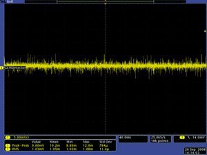
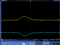
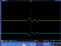
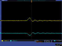
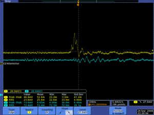
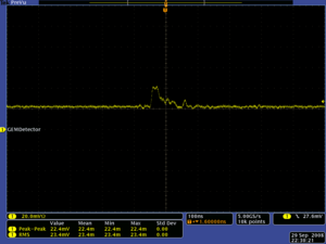
GEM Detector HV settings and Pulses
| GEM Drift HV (Volts) |
GEM Drift current [math]\mu[/math] A |
GEM foil HV (Volts) |
GEM foil current [math]\mu[/math] A |
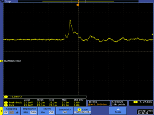
Scope Picture
|
| 3950 |
3650 |
882 |
|
| 3900 |
3600 |
870 |
|
| 3850 |
3550 |
859 |
|
| TGEM Drift HV (Volts) |
TGEM Drift current [math]\mu[/math] A |
TGEM foil HV (Volts) |
TGEM foil current [math]\mu[/math] A
|
| 3600 |
|
3300 |
|
SIS310
1.) Get 100 Ohm resistors
2.) Get Bread board
Go Back


