Lab 6 Pulses and RC Filters
Differentiator
1.) Adjust the pulse generator to output square pulses which at [math]\tau[/math] sec in time.
Possible capacitors
- [math]C_1 = 1 \times 10^{-6} F[/math]
- [math]C_2 = 10.24 \times 10^{-9} F[/math]
Possible Resistors
- [math]R_1 = 1 \times 10^3 \Omega[/math]
- [math]R_2 = 14.35 \times 10^{3} \Omega[/math]
- [math]R_1 C_1 = \tau_1 = (1 \times 10^3 \Omega ) (1 \times 10^{-6} F )= 0.001[/math] s
- [math]R_1 C_1 = \tau_2 = (14.35 \times 10^{3} \Omega)(10.24 \times 10^{-9} F )= 1.46 \times 10^{-4}[/math]
- [math]\omega_1 = 100 rad/sec \Rightarrow \nu_1 = 100/2\pi = 16 Hz[/math]
- [math]\omega_2 = 6805 rad/sec \Rightarrow \nu_2 = 1083 Hz[/math]
tek012
- [math]R_1 C_1 =10 \tau_2 = 1460 \mu s[/math]
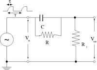
2.)Construct the circuit below selecting an RC combination such that RC [math]\approx[/math] 1/10
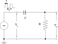
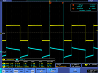
3.)Measure[math] V_{in}[/math] and [math]V_{out}[/math]. Sketch a picture comparing[math] V_{out}[/math] and [math]V_{in}[/math].
4.) Change the pulse width such that [math]RC = \tau[/math]
5.)Measure[math] V_{in}[/math] and [math]V_{out}[/math].Sketch a picture comparing[math] V_{out}[/math] and [math]V_{in}[/math].
6.) Change the pulse width such that[math] RC = 10 \tau[/math]
7.)Measure [math]V_{in} and V_{out}[/math].Sketch a picture comparing[math] V_{out}[/math] and [math]V_{in}[/math].
 |
 |

|
| [math]RC =\tau/10 = 14.6 \mu s[/math] |
[math]RC =\tau = 146 \mu s[/math] |
[math]RC =10 \tau = 1.460[/math]ms
|
| [math]RC \gt \gt \tau [/math] |
[math]RC =\tau [/math] |
[math]RC \lt \lt \tau [/math]
|
Questions
1.) What happens if the amplitude of [math]V_{in}[/math] is doubled.
V_{out} is doubled if V_{in} is doubled.
2.) What happens if R is doubled and C is halved?
Nothing, RC time constant remains the same.
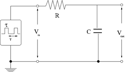
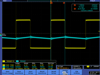
Integrator
Now repeat the above experiment with the resistor and capacitor swapped to form the low pass circuit below.
 |
 |
|
| [math]RC=\tau/10 = 14.6 \mu s[/math] |
[math]RC =\tau = 146 \mu s[/math] |
[math]RC =10 \tau = 1.460[/math]ms
|
| [math]RC \gt \gt \tau [/math] |
[math]RC =\tau [/math] |
[math]RC \lt \lt \tau [/math]
|
Pulse Sharpener
The goal of this section is to demonstrate how well the circuit below can sharpen an input pulse
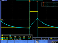
1.) The first step is to create an input pulse which is rounded, similar to the output of the integrator circuit when RC = 10 [math]\tau[/math]. You can do this using a capacitor shorted across the output of the pulse generator. This will essential be coupled to the input impedance of the pulse generator and form a low pass circuit.
As a result the input voltage is given as
- [math]V_{in} = V_0 \left ( 1 - e^{-t/\tau}\right )[/math]
where
- [math]\tau=R_{out} C_{out}[/math]
- [math]R_{out}[/math] = impedance of the function generator at output which produces V_{in}
- [math]C_{out}[/math] = capacitor shorting the function generator output to ground (not shown in the above picture)
- [math]e^{-t/\tau} = e^{-1} = =0.36788[/math]
[math]C_{out} = 1.210 \pm 0.005 \times 10^{-6} F[/math]
I measure the times constant by looking how long it take the 2 Volt pulse to rise to (1-e^{-1}) =1.26 V
- [math]\tau = 60 \times 10^{-6}[/math]
- [math]R = \tau/C = 60 \times 10^{-6} s/ 1.210 \times 10^{-6} F =49.6 \Omega[/math]
A second measurement:
- [math]\tau = 70 \times 10^{-6}[/math]
- [math]R = \tau/C = 70 \times 10^{-6} s/ 1.210 \times 10^{-6} F =57.9 \Omega[/math]
I would say the input impedance of the BK precision function generator is about 50 [math]\Omega[/math].
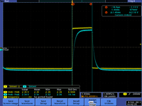
2.) The output should be given by
- [math]V_{out} = V_0^{\prime} \left ( 1 - e^{-t/\tau^{\prime}}\right )[/math]
where
- [math]\tau^{\prime} = \left ( \frac{R_1 R}{R_1+ R}\right ) C_1[/math]
3.) Make measurements of the rise time [math]\tau[/math] and [math]\tau^{\prime}[/math]. The rise time is defined as the time it take the pulse to go from 10% of its max value to 90% of its max value.( 5 pnts.)
4.) Compare the measurement of [math]\tau^{\prime}[/math] to what you expected based on your measured values of [math]C_1[/math], [math]R_1[/math] and[math] R[/math].( 15 pnts.)
Questions
1.) Qualitativly, why is [math]\tau^{\prime} \lt \tau[/math]?( 10 pnts.)
- [math]\tau^{\prime} = \left ( \frac{R_1 R}{R_1+ R}\right ) C_1 = \left ( \frac{R_1 }{R_1+ R}\right )\tau[/math]
2.) How is [math]V_{out}[/math] worse than [math]V_{in}[/math]( 10 pnts.)
- [math]V_{out} = V_0^{\prime} \left ( 1 - e^{-t/\tau^{\prime}}\right ) = \left ( \frac{R_1 }{R_1+ R}\right ) V_0\left ( 1 - e^{-t/\tau^{\prime}}\right )[/math]
Forest_Electronic_Instrumentation_and_Measurement


