Difference between revisions of "TF EIMLab6 Writeup"
| Line 33: | Line 33: | ||
| [[File:TF_EIM_L6_RC10t.png|200px]]||[[File:TF_EIM_L6RCt.png| 200px]] || [[File:TF_EIM_L6RC0.1t.png|200px]] | | [[File:TF_EIM_L6_RC10t.png|200px]]||[[File:TF_EIM_L6RCt.png| 200px]] || [[File:TF_EIM_L6RC0.1t.png|200px]] | ||
|- | |- | ||
| − | |<math>R_1 C_1 = | + | |<math>R_1 C_1 =\tau/10 = 14.6 \mu s|| <math>R_1 C_1 =\tau = 146 \mu s</math> || <math>R_1 C_1 =10 \tau = 1.460</math>ms </math> |
|} | |} | ||
Revision as of 23:36, 8 February 2011
Lab 6 Pulses and RC Filters
Differentiator
1.) Adjust the pulse generator to output square pulses which at sec in time.
Possible capacitors
Possible Resistors
- s
tek012
 |
 |
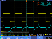
|
| ms </math> |
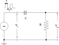
2.)Construct the circuit below selecting an RC combination such that RC 1/10
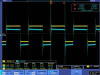
3.)Measure and . Sketch a picture comparing and .
4.) Change the pulse width such that
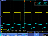
5.)Measure and .Sketch a picture comparing and .
6.) Change the pulse width such that
7.)Measure .Sketch a picture comparing and .
Questions
1.) What happens if than amplitude of is doubled.
2.) What happens if R is doubled and C is halved?
Integrator
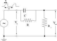
To illustrate the integrator circuit we need to have an input pulse which looks like the output of the above differentiator circuit. In other words, input a pulse whose output is obviously the integral of the input pulse.
