Difference between revisions of "TF EIMLab5 Writeup"
| (2 intermediate revisions by the same user not shown) | |||
| Line 32: | Line 32: | ||
#What is the bandwidth of the above circuit? (5 pnts) | #What is the bandwidth of the above circuit? (5 pnts) | ||
| + | |||
| + | Bandwith represent the range of frequencies over which the signal can be transmitted through the circuit. In this case we will define transmission as signals which are about half the peak power of the max amplitude signal that is transmitted through the circuit. | ||
| + | |||
| + | Since P = I^2 R the power is half when the circuit's current is \frac{1}{2} of I_{max} | ||
| + | |||
| + | Since I \propto V, we want to find the vrequencies where V_{out} is cut in half of its max Value V_{max} | ||
=The RLC cicuit= | =The RLC cicuit= | ||
[[File:TF_EIM_Lab5_RLC.png| 200 px]] | [[File:TF_EIM_Lab5_RLC.png| 200 px]] | ||
#Design and construct a '''series''' LRC circuit. | #Design and construct a '''series''' LRC circuit. | ||
| − | + | ||
| − | + | {| border="1" |cellpadding="20" cellspacing="0 | |
| + | |- | ||
| + | | Element || Value | ||
| + | |- | ||
| + | |L || 33 \mu H | ||
| + | |- | ||
| + | |C|| 1.024 \mu F | ||
| + | |- | ||
| + | |R ||1 k \Omega | ||
| + | |- | ||
| + | |R_L ||2 k \Omega | ||
| + | |- | ||
| + | |} | ||
| + | |||
| + | 2Measure and Graph the Gain as a function of the oscillating input voltage frequency. (25 pnts) | ||
| + | |||
| + | 3.)Measure and Graph the Phase Shift as a function of the oscillating input voltage frequency. (25 pnts) | ||
==Questions== | ==Questions== | ||
| − | + | 1.)What is the current <math>I</math> at resonance? (5 pnts) | |
| − | + | ||
| + | At resonance the current through R is a maximum so the circuit is a voltage divider. | ||
| + | |||
| + | I = V/(R+R_L) | ||
| + | |||
| + | 2.)What is the current as <math>\nu \rightarrow \infty</math>? (5 pnts) | ||
| + | |||
| + | At infinite frequency the current will drop to zero as the circuit is unable to respond fast enough before the current changes direction. | ||
[[Forest_Electronic_Instrumentation_and_Measurement]] | [[Forest_Electronic_Instrumentation_and_Measurement]] | ||
Latest revision as of 16:46, 27 March 2011
LC Resonance circuits
The LC cicuit
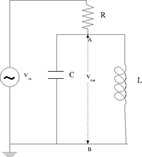
1.) Design a parallel LC resonant circuit with a resonant frequency between 50-200 kHz. use = 10 - 100 , R = 1k .
| Element | Value |
| L | 33 \mu H |
| C | 1.024 \mu F |
| R | 1 k \Omega |
| R_L | 2 k \Omega |
2.Construct the LC circuit using a non-polar capacitor
3. Measure the Gain as a function of frequency. (25 pnts)
4. Compare the measured and theoretical values of the resonance frequency () (10 pnts)
Questions
- What is the bandwidth of the above circuit? (5 pnts)
Bandwith represent the range of frequencies over which the signal can be transmitted through the circuit. In this case we will define transmission as signals which are about half the peak power of the max amplitude signal that is transmitted through the circuit.
Since P = I^2 R the power is half when the circuit's current is \frac{1}{2} of I_{max}
Since I \propto V, we want to find the vrequencies where V_{out} is cut in half of its max Value V_{max}
The RLC cicuit
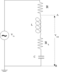
- Design and construct a series LRC circuit.
| Element | Value |
| L | 33 \mu H |
| C | 1.024 \mu F |
| R | 1 k \Omega |
| R_L | 2 k \Omega |
2Measure and Graph the Gain as a function of the oscillating input voltage frequency. (25 pnts)
3.)Measure and Graph the Phase Shift as a function of the oscillating input voltage frequency. (25 pnts)
Questions
1.)What is the current at resonance? (5 pnts)
At resonance the current through R is a maximum so the circuit is a voltage divider.
I = V/(R+R_L)
2.)What is the current as ? (5 pnts)
At infinite frequency the current will drop to zero as the circuit is unable to respond fast enough before the current changes direction.

