Preparing Drift Chamber Efficiency Tests
Preparing Drift Chamber Efficiency Tests
Since the Differential Cross-Section for Moller scattering is well known in the center of mass frame of reference, a conversion to the detector's lab frame of reference will need to occur. To ensure that the GEMC detector is fed a Moller LUND file for the differential cross section, the center of mass frame LUND information must be converted to the lab frame equivalent. Using the expression for the differntial cross-section:
where,
A beam of electrons with a constant energy impinging on a stationary electron in the lab frame can be converted to the center of mass frame energies which by definition must be equal. Since the Energy in the CM frame is constant in so long as the incoming electron energy is constant, we should be able to cycle through only the scattering angle theta to obtain the differential cross-section.
For the GEMC detector to simulate a given distribution, a LUND file must be created. LUND files can pass information about position and momentum, but not angle, in the lab frame. Assuming a constant position at the vertex, this implies that we will need to cycle through the momentum components for the scattered and Moller electrons in the CM frame to vary angle theta in the lab frame. The CM frame also implies that the total momentum for the scattered and Moller electron be equal but opposite.
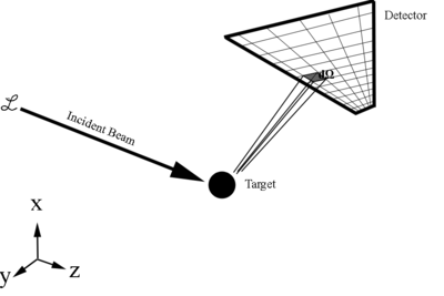
From the definition of the differential cross-section:

Since this is just a ratio of detected particles to total particles, this gives the cross section as a relative probablity of a scattering to occur. Using the idea of a probability for the Moller differential cross-section distribution, an isotropic distribution of theta in the CM can be constructed, and a weight factor applied to give us the Moller differential cross-section as a function of the scattering angle theta in CM. The particles can be Lorentz transformed to the lab frame after a collision, and the appropriate weight stored in a variable within the LUND file. Hits in the drift chamber can be correlated with the LUND events and the associated weight to rebuild the differential cross-section to see how well it correlates with the Moller differential cross section.