PhD Proposal Tamar
Tamar PhD Proposal
Abstract
Introduction
Physics Motivation
Deep inelastic scattering of electrons(leptons) on hadrons is a powerful tool for understanding the structure of the nucleon. For large four-momentum square (momentum transfer) the inelastic scattering can be considered as the incoherent sum of the elastic scattering off the hadron constituents, the pointlike patrons. For example the proton constituents are u(up) and d(down) quarks in the quark parton model. However QCD predicts existence of other patrons in the nucleus. The electron is not sensitive to strong interactions, because of that it can only probe hadron constituents which carry electric or weak charges.
In the Deep Inelastic scattering the high energy electron with initial energy E and four-momentum l, b exchanging a virtual photon, is scattered off a hadron, which is at rest in the lab system, with mass M and four-momentum p. The scattering angle of the electron is , measured from the incoming electron beam. The final state of the system is described by the four-momentum of the scattered electron and of the nucleon with invariant mass W. The kinematics of DIS can be described with four-momentum transfer square, the energy transfer and the Bjorken scaling variable. The four-momentum transfer is a measure of the magnifying power of the lepton probe. The probed distance scale can be written in terms of Q:
??????????????????????????????????????????????????????
As it was mentioned above in the DIS an interaction doesnt happen with the hadron as a whole, but with exactly one of its constituents. Each quark(constituent) carries the fraction four-momentum of the nucleon with probability density is the probability finding the ith quark with fraction of the proton(neutron) four-momentum. Assuming all this the structure functions can be written as sum of the elastic structure fractions weighted by the . Taking in consideration that the mass of the ith quark is also the fraction of the nucleon mass :
and
The DIS between the unpolarized electron and nucleon can be described in terms of two so called structure functions and :
The Callan-Gross relation between the F_1 and F_2 is following:
"The structure function F_1 measures the parton density as function of x while describes the momentum density, both weighted with the coupling strength to the photon probe."
In the proton the distributions of up and down quarks are defined as u(x) and d(x), the same for neutron. The are two types of quarks: valence and sea quarks , assuming that . The constituent quark model (QPM too) states that the proton(neutron) for example contains two up(down) and one down(up) quarks. So in the proton, summing over all the constituents should give us following:
and
The electromagnetic structure function for proton and neutron can be expressed in terms of quark distribution functions:
can be obtained from by replacing u->d and vice versa.
From the last two equations the structure functions for proton and neutron can be expressed in terms of valence quark distribution functions:
and
For most of the fixed-target experiments, like eg1b, the spin asymmetry is given by the ratio of the polarized structure function to the unpolarized: , where the polarized structure function is similar of the unpolarized structure function. As it is known the spin asymmetry and unpolarized structure function are measurable quantities and through them one can determine :
- \Delta q = q{arrowup} - q {arrow down}
The polarized cross sections, which are related to the polarized structure function, are not measured directly. However the asymmetry related to them can be easily determined from the measurements:
where () is the photon absorption cross section ones whose spin is antiparallel(parallel) to the target polarization. The photon of spin 1 is absorbed by only quarks whose spin is in the opposite direction from the photon's spin. Therefore, the polarized structure function can be related to the difference of these cross sections. However, the unpolarized structure function is the some of those two cross sections. The structure functions described above is based on quark parton model, where the contribution from the sea quarks is minimized. The double spin asymmetry can be written in terms of valence quark distribution functions for proton and neutron targets in this kinematic range:
- (1)
- (2)
- (1)
///////////////////////////////////////////////////////////////////////////////
Electron-nucleon semi-inclusive scattering, where the scattered electron and one or more hadrons are detected in coincidence, is a powerful tool for understanding the structure of nucleons. In a semi-inclusive experiments the four-momentum square and other variables can be determined by the scattered lepton energy and the scattering angle. The polarized structure function, which is a helicity difference quark number density, depends on this measurable variables.
/////////////
The structure functions can be expressed in terms of Bjorken scaling variable, which is a fraction of the nucleons momentum carried by the parton. In SIDIS "an energetic virtual photon, the probe, gets emitted and interacts with the quarks inside the nucleon. The energy and momentum transfer is so large that the quark being struck is expelled from the nucleon. Thus the nucleon breaks apart, which is one major difference between such a deep inelastic scattering event and an elastic scattering event in which the nucleon stays intact. The various fragments of the nucleon then form new hadrons(particles which are made of quarks) until all the energy of the photon is used up. As the expelled quarks will usually carry most of the energy of the photon, one can look for the most energetic hadrons to obtain clues about those quarks. For instance, the positively charged up quark prefers to form a meson which itself contains an up quark. Similarly the negatively charged down quark most likely forms a meson".
"The extraction of polarized quark distribution functions from semi-inclusive asymmetries can be done using the method based on the extraction of spin asymmetries in the difference of and counts".
/////////////
list out some of the reasons for the above statement and then convert the list into a paragraph

1.) measure polarized quark distribution functions?
2.) test fragmentation?
3.)
4.)
Models provide better understanding of the nucleon structure and "play an important role " in the explanation of the experimental data. Measurement of the double spin asymmetry and the ratio of the polarized valence down quark distribution function to the unpolarized can be used to see the difference between the numerous descriptions of the nucleon structure. pQCD and a hyperfine perturbed constituent quark model predict the scaling variable x_b = 1 corresponds to A_N~1. On the other hand, the well-studied SU(6) constituent quark model for x_b=1 state that A_p=5/9 and A_n=0. The inclusive double spin asymmetry can be written in terms of valence quark distribution functions:
where deltaq_v and q_v are polarized and unpolarized valence quark distribution functions. Quark distribution function q(x) is the probability(density) of finding a quark with fraction x of the proton(neutron) momentum.
The semi-inclusive pion electro-production asymmetries can be written in terms of the valence quark distributions
= (3)
= (4)
where
= (5)
Experimental Setup
The CEBAF Large Acceptance spectrometer is a detector at Thomas Jefferson National Accelerator Facility which covers particle detection almost on 360 degree. The detector is divided into six sectors, each of them including a superconducting coil, which produce a toroidal magnetic field along the beam direction. As a charge particle tracking system was used a set of drift chambers divided by three regions, totally consisting of 18 drift chambers. After the drift chamber system the CLAS detector is equipted with Cherenkov counter for seperating electrons from the pions and with scintillators for determination of the Time of Flight of a charge particle. At the end of the detector the particle identification and timing(resolution) is achieved using electromagnetic calorimeters. Five different targets were used during the experiment: , ,C12, liquid He-4 and frozen N15. In order to remove background from the first two types of target the measurements were done with last three targets listed above.
Target
- Target Materials
The EG1 experiment at Jefferson Lab used five different targets to measure polarized structure functions of the nucleon and perform background corrections. The main target materials for the experiment used frozen ammonia, , for the polarized protons and deuterated ammonia, for the polarized deuterons. The target vessel, known as the target ladder, was designed and built by collaboration of the Italian Istituto di Fisica Nucleare, TJNAF, Oxford instruments and the University of Virginia. The solid targets(NH3 and ND3) were polarized using the method of Dynamic Nuclear Polarization <ref>Prok Thesis</ref>. Three other targets, C12, liquid He-4 and frozen N15 were used to remove the Nitrogen background from NH3 and ND3 target data.
there is a figure of merit which considers max polarization and radiation damage, Li-6 is a competitor
Ammonia targets were selected because of their ability to produce high polarization and they are less effected by beam radiation. On the other hand, the damage caused by this radiation can be repaired by annealing. The target is warmed up to liguid nitrogen temperature for annealing. In addition, the ammonia target has a high ratio of free nucleons (~3/18) approximately 16.5 % for and 26.6 % for . One disadvantage of choosing ammonia is the polarization background caused by 15N(spin - 1/2), or 14N(spin - 1), which was accounted for by taking data using a solid N-15 target.[SChen_FSU_thesis]
- Magnet
A 5 T magnetic field is established using a produced pair of superconducting Helmholtz coils oriented such that the magnetic field is parallel to the beam direction. The field induces the hyperfine splittings needed to polarize the target material using ? Ghz RF waves. The uniformity of the field is varying less than over a cylindrical volume of 20 mm in diameter and length. This configuration is necessary for DNP. The particles with scattering angles between 0-50 are detected in the CLAS as well as 75-105 due to the 8 cm gap between the Helmholtz coils. The target magnetic field does not interact with the electron beam, however it is effective in shielding the drift chambers from the low energy Moller electrons.The target field bents the scattered particles in the azimuthal direction and it falls rapidly with distance as (). The effect of magnetic field at the drift chambers is negligible.[ref 2]
The CEBAF Large Acceptance spectrometer
- The Torus Magnet
The torus magnet for CLAS detector consists the six superconducting coils located around the beam line in a toroidal geometry, producing the magnetic field in the direction. Each magnetic coil defines the sector of detector. So the CLAS detector has six sectors(spectrometer). The system of the magnet is defined in spherical coordinates where the z-axis are along the beam direction and the x and y axis along the horizontal and vertical plane normal to the beam line.
The maximum current for the CLAS magnet is 2860 A, in the forward direction the total magnetic field is 2.5 T-m and at a polar scattering angle with 90 degrees 0.6 T. The magnet itself is around 5 m in diameter and 5 m in length. The coils of the magnet are cooled by liquid helium circulating through cooling tubes to a superconducting temperature of 4.5 K.[[Yelena Alexsandrovna Pork, Measurement of The spin Structure Functions of The Proton in The resonance Region.]]
One can find out the charged particles momentum knowing the trajectory of a particle. In Eg1b experiment, the operated torus values were: 2250, -2250, 1500, -1500.
- Drift Chambers
In order to track the charged particles in the EG1b experiment a drift chamber system is used. A drift chamber is a particle tracking detector that measures the drift time of ionization electrons in a gas to calculate the spacial position of an ionizing particle.
The electric field in a drift chamber is produced by the anode(sense wire) and cathode(field wire) wires. The charge particle traveling trough the drift chamber ionizes the gas, producing the electrons that drift to the anodes. After time(drift time) electrons are collected at the anode(sense wire) generating the pulse at t time. The distance from the traversing particle to the sense wire can be calculated using the drift time and velocity.
The drift chamber system in CLAS detector is divided into three regions, each consisting six separate chambers(six sectors). Region 1 (R1) chambers are placed closest to the target, where the magnetic filed is low. Region 2 (R2) chambers are in a high magnetic field region, they are located between the magnetic coils. Region 3 (R3) chambers are outside the torus coils and they are largest ones. The drift chambers contain three type of wires stretched between the endplates: sense, guard and field. The endplates are attached to the drift chamber so that the angle the form is equal to 60 degrees. Each drift chamber is subdivided into two separate superlayers. Each superlayer with six layers of drift cells, and each drift cell with one sense wire surrounded by six field wires forming a hexagonal shape([1]). Each superlayer is surrounded by guard wires at a positive potential to stimulate the electric field caused by the drift cells. The sense wire is operated at positive potential and the field wire at negative. In each superlayer the distance between the sense and field wire increases with the radial distance from the target. In R1 the average distance between the sense and field is 0.7 cm, in R2 1.15 cm and in R3 2.0 cm.
The gas used to fill the CLAS drift chamber is a 90 - 10 % mixture of the argon(Ar) and , where Ar has an ionization gain of . Inside the drift chamber the constant pressure is provided by outflowing the gas. The chamber endplates are equipped with the circuit board with a single channel differential pre-amplifier for each sense wire.
- Cherenkov detector
The threshold CLAS Cherenkov detector is used to distinguish electrons from pions. The mixture gas used to fill the Cherenkov counter is perfluorobutane gas at atmospheric pressure. The advantage of Perfluorobutane gas is its high index of refraction n=1.00153, which results in a high photon yield and the following energy thresholds. The threshold for the Cerenkov radiation can be written as , or for energies , where v is the velocity of charged particle, n index of refraction for the medium, c speed of light and . In our case , accordingly one can calculate the energy threshold for different charged particles, for electrons it is 9 MeV and for pions 2.5 GeV.
The Cherenkov detector was designed to maximize the coverage in each of the sectors up to an angle degrees.The CLAS Cherenkov DetectorG. Adamsa, V. Burkertb
As a light collector were used the system of mirrors , the light collecting cones and photomultiplier tubes(PMTs). In the extreme regions of the angular acceptance of the spectrometer the number of detected photoelectrons is too low. To get acceptable efficiency of the detector in these regions photomultiplier tubes were placed. The calibration of the Cherenkov detector is in terms of the collected number of photoelectrons.
- Scintillators
The CEBAF Large Acceptance Spectrometer (CLAS) is equipped with 288 scintillator counters. The purpose of the scintillator is to determine the time of flight for the charged particles and to trigger it in coincidence with another detector system for the particle identification. The time of flight system is built so that time resolution at small polar angles ps and at angles above 90 degrees ps. This time resolution helps to discriminate pions and kaons up to 2 GeV/c.
The time of flight system is located between the Cherenkov detectors and electromagnetic calorimeters. The scintillator strips(BC_408) are located perpendicularly to the average particle trajectory with an angular polar coverage of 1.5 degrees. Each sector of The CLAS detector consists of 48 scintillator strips with a thickness of 5.08 cm. The length of the scintillators varies from 30 cm to 450 cm and the width is between 15 cm at small polar angles and 22 cm for the large angles.
- Calorimeter
The CLAS detectur contains 8 modules of electromagnetic calorimeter. A calorimeter is a device that measures the total energy deposited by a crossing particle. They are useful in detecting neutral particles and distinguishing between electrons and hadrons due to their different mechanism of depositing energy. The CLAS calorimeter has three main functions:
1) detection of electrons at energies above 0.5 GeV;
2) detection of photons with energies higher than 0.2 GeV;
3) detection of neutrons, with discrimination between photon and neutrons using time-of-flight technique.
6 calorimeter modules of the CLAS detector are placed in each sector in the forward region (polar angle of 10-45 degrees, forward angle calorimeter), while the other two modules are located at large angles in sectors 1 and 2(50-70 degrees, large angle calorimeter). The forward calorimeter has a lead/scintillator thickness ratio 0.2, with 40 cm of scintillators and 8 cm of lead per module. The lead-scintillator sandwich is shaped as a equlaterial triangle in order to match the hexagonal geometry of the CLAS detector. It is made of 39 layers of a 10 mm BC_412 scintillator and lead sheet of thickness of 2.2 mm. Each scintillator layer contains 36 strips parallel to one side of the triangle, with this configuration each orientation is rotated by 120 degrees from another one. This gives three views each containing 13 layers providing stereo information of the location of the energy deposition.
To improve hadron identification, there was provided longitudinal sampling of the shower. Each set of 13 layers were subdivided into an inner 5 layers and outer 8 layers stack.
Preliminary Results
The differential cross-section and electron beam asymmetries were measured using the CEBAF Large Acceptance spectrometer (CLAS) at Thomas Jefferson National Lab with a 5.7?? GeV continues electron beam of luminosity and polarized target(frozen ammonia) and compared to the E99-107 data.
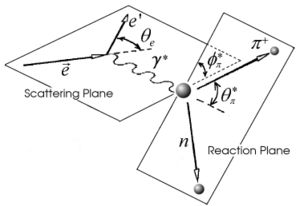
The kinematics of single pion electroproduction can be described by five variables: the virtual photon negative four-momentum transfered squared , W invariant mass of the photon-nucleon system, the polar and the azimuthal angle of the outgoing pion in center of mass frame and the scattered electron azimuthal angle.
The four-momentum transfered squared , where k(E) nd () are the initial and final four-momentum(energy) of the electron in the laboratory frame and - electron scattered angle. The invariant mass , where and are four-momenta of the virtual photon and target respectively, is proton mass and the virtual photon energy.
The five-fold differential cross section can be written in the following way for a single pion electroproduction:
where represents the efficiency of the cherenkov detector, - the integrated luminosity, is the acceptance factor and the Jacobian term can be expressed in terms of the initial and final energy of lepton:
- Cuts
In the semi-inclusive asymmetry analysis scattered electrons are used. The contamination in the electron sample is removed using the cuts on the energy deposited in the electromagnetic calorimeter, the number of photoelectrons in the Cherenkov counter and fiducial cuts(there should be vertex cut too).
the energy deposition in the calorimeter for electrons and pions is different. Pions are minimum ionizing charge particles and energy deposited into the calorimeter, independent of the particles momentum is constant. It is approximately ~ 0.08 GeV. On the other hand, electrons produce photoelectrons and create electromagnetic shower releasing the energy into the calorimeter which is proportional to their momentum. In order to remove contamination due to the energy deposition in the calorimeter the following cut was introduced: . The cut was also applied to the energy collected in the inner part of the calorimeter: , because the ratio of the energy deposited in the total to the inner calorimeter depends on the thickness of the detector and is a constant.
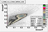
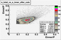
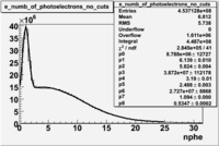
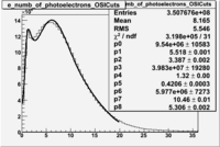
In addition to the cut on the energy deposited into the electromagnetic calorimeter, the misidentified electrons were excluded requiring a signal in the threshold CLAS Cherenkov detector, which is used to distinguish electrons from pions up to 2.5 GeV momentum of the particle. The energy threshold for electrons in the Cherenkov counter is 9 MeV and for pions 2.5 GeV. There are no many pions above 2.5 GeV momentum(should rewrite). A bad recollection of the cherenkov light that occurs for a particular kinematics is responsible for a faulty peak around ~1.5 on the number of photoelectons distribution shown below. To eliminate the faulty peak and high energy pions, which have enough energy to produce photons the geometrical cuts were applied on the data. The second histogram below shows that after cuts the peak around 1.5 disappears. (i need to discuss about nphe>2.5 cut)
| No cuts | OSI Cuts |
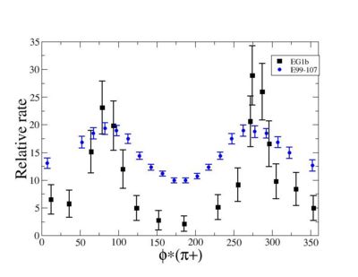
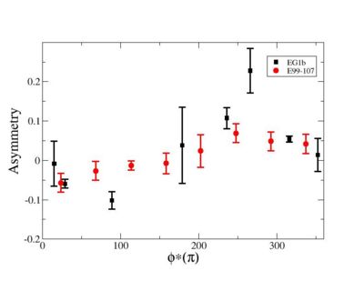
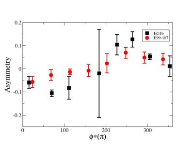
Because of wide range of kinematics, was measured only for certain lepton scattering ?? angle and W invariant mass. Applying above described cuts: EC_inner>0.06, EC_tot/p>0.2, nphe>2.5 and , for he following invariant mass and the vs relative rate distribution is shown below on the graph and compared with E99-107 data.
- Electron Beam Asymmetry


