Performance of THGEM as a Neutron Detector
Title
The Performance of Thick Gaseous Electron Multiplier (THGEM) Preamplifiers as a Neutron Sensitive Detector.
Introduction
I propose to construct and measure the performance of a fission chamber instrumented with preamplifiers known as a Thick Gas Electron Multiplier (THGEM). This fission chamber is a chamber filled with a 90/10 Ar/ gas mixture enclosing a fissionable target material, like Uranium or Thorium. A neutron of sufficient energy has the potential to interact with fissionable material producing heavy ions known as fission fragments. The fission fragments within 5 micron of the target's surface may escape the target as ions and ionize the gas in the chamber. Electrons freed from the ionization gas can enter the THGEM preamplifier producing secondary electrons which are directed to collectors using strong electric fields.
A THGEM preamplifier is a perforated fiberglass board (PC board) clad with a conducting material. The design is based upon the Gas Electron Multiplier (GEM) invented by Fabio Sauli in 1997<ref name="Sauli1997">F. Sauli, et al, NIM A386, (1997) 531-534 </ref >. The GEM preamplifier is a 50 micron sheet of kapton that is coated on each side with 5 micron of copper. The copper clad kapton is perforated with 50-100 micron diameter holes separated by 100-200 micron in a staggered array . The THGEM preamplifier is a more macroscopic version of GEM that uses a 2 mm thick fiberglass sheet perforated with holes that are 2 mm in diameter.
Strong electric fields are established by supplying a potential difference between the two sides of the kapton, or the fiberglass for the case of the THGEM. The electric field lines transport liberated electrons through the preamplifier holes. For the GEM foils, the smaller diameter of the hole can provide sufficient amplification using a potential difference of 350 V between the two sides. On the other hand, the THGEM with the larger hole diameter requires a higher potential difference of about 2000 Volts to achieve similar amplifications.
The objective of this work will be to construct a THGEM based ionization chamber. The THGEM will follow a proven design <ref name="Agocs">G. Agocs, B. Clark, P. Martinego, R. Oliveira, V. Peskov,gand P. Picchi,JINST, 3, P020112, 2008 </ref > and use a resistive paste to reduce discharge events. The detector may be made sensitive to neutrons by doping the resistive paste with a fissionable material. The doping step will take place once a working THGEM equipped detector has been demonstrated. This fission chamber-like device will have the advantage of measuring the location of the incident neutrons that induced a fission event within the chamber by measuring the ionization signal using a segmented charge collector.
Chapter One
- The source of the free electrons in the gas appear as a result of many physical processes, these process are related to primary ionization or secondary ionization , photoionization, thermal ionization, deionization by attachment (negative ion formation) are sources for primary ionization in the gas, but photoelectric emission, electron emission by by excited atoms or positive ion,and field emission <ref name="Kuffel"/>.
- According to the gas physical properties the previous processes may differ in the value in the cross section, for example mixing argon gas with carbon dioxide will make the gas faster, since all the photons emitted by the argon gas after the ionization and the electron multiplication will be absorbed by carbon dioxide molecules<ref name="Veenhof"> R.Veenhof, Internal Note/TPC, ALICE reference number ALICE-INT-2003-29 version 1.0 </ref >.
Why 90/10 Ar/CO2 Mixture (Simulation by Garfield) <ref name="Veenhof"/>
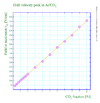
- Drift velocity: Increasing the percentage of CO2 the gas mixture at low electric field increases the drift velocity as shown in the figure:
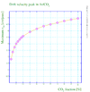
The drift velocity is saturated but at different values depending the percentage of the CO2, so the increase in the drift velocity becomes smaller withe increase in CO2 percentage int he gas mixture as show in the figures below:
- Gain: Dependent Townsend coefficients, the figure below shows the gain-Electric field relationship for different mixtures of ArCO2, in addition to the effect penning of the gain.
Gas Quenching
Rewrite the first two sentences so quenching is more clearly described.
Gas quenching is a non-ionizing process occurs when a gas molecules with large cross sections for excitation and vibration states decrease a charged particle energy to create any ionization when the charged particle passes through. Usually, the gas mixture ,contains the ionization event, consists mostly of gas atoms as a main source of electrons and the quenching gas, when the free electrons are scattered after the ionization, their energy is decreased by quenching so the number of secondary electrons becomes less, Consequently, a higher voltage is required to get a gain from this mixture than a medium only has a non-quenching gas<ref name="Sharma"> A.Sharma,F. Sauli, first Townsend coefficients measurements for argon gas european organization for nuclear research (1993) </ref >.
Not only does the quenching process decreases the electron energy, but also decreases the positive ions energy (produced by ionization) when the ions collide with these gas molecules and emits a photon or more from these positive ions. These photons represent the energy loss in a form other than the ionization which is called argon escape peak in case of using Argon gas.
Gas quenching experimentally can be measured by evaluating Townsend first coefficients A,B for different gas mixtures. The following table represents the Townsend first coefficients' values for different ratio of Ar/CO2 gas mixtures<ref name="Sharma"/>:
| Percentage of CO2 | 3.7 | 22.8 | 87.2 | 100 |
| A | 5.04 | 221.1 | 158.3 | 145.1 |
| B | 90.82 | 207.6 | 291.8 | 318.2 |
| 16.2 | 21.6 | 32.9 | 36.4 |
The electric field pressure ratio in the last row is the upper limit of the reduced electric field which Townsend's equation fits considering E as a uniform electric field.
Decreasing the discharge in THGEM
THEGM preamplifier is designed to be rebust, economical, and to get the maximum gain with the least discharge effect.
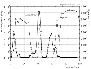
The discharge effect is when you experimentally start observing sparks coming from the detector. Whenever discharge becomes phenomenon to study then the probability of discharge is used. The probability of discharge is defined as the ratio between the observed frequency of the breakdown and source rate <ref name="bachmann"/>.The discharge rate and the source rate can be represented as function of position as shown in the figure.
Producing these sparks refers to many reasons,it is obviously observed when a highly ionizing ion passes through the gaseous chamber and produces enough free electrons to break down the rigidity of surrounding gas by having an avalanche size exceeds Raether limit ( electron-ion pairs) when separating the electrodes vertically with small a distance <ref name="bachmann"> Bachmann et al NIM A 479 (2002) 294-308 </ref > .
Temperature, humidity, and gas flow externally affect the probability of the transition from the proportional multiplication to a discharge at a given potential, the effect clearly appears in absence of the amplification internal effects as the design quality and the history of the electrodes <ref name="bachmann"/>.
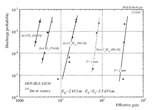
In case of heavily ionizing ions like alpha particles, an increase in gain causes the probability of discharge to increase, but the increment in the probability of discharge can be decreased by choosing an appropriate gap between the THGEM cards <ref name="bachmann"/>. As a result, achieving a maximum gain for an incident particle on a chamber with a specific gas mixture ,under a voltage applied on the THGEM cards, requires an appropriate distance that increases with increment of the ionization rate, i.e an alpha particle requires a bigger gap between the THGEM cards than that of a gamma ray to avoid the discharge effect.(can be experimentally proven).
Townsend's Coefficients
Townsend's First Coefficient
Townsend's first Coefficient is defined as "the number of produced by an electron per unit length in the direction of the electric field"<ref name="Kuffel"/>.
- Townsend started his investigations about discharge after fundamental studies were known around 1899 about:
1- Conductivity production by x-rays.
2- Diffusion coefficients, mobility of ions and ion-electron recombinations.
- It was observed for an increment in Electric filed E and pressure P beyond the saturation current value, at some critical value of E and p, the current increases rapidly which will lead to a breakdown of the gap in the form of a spark <ref name="loeb"> L.B.Loeb, basics processes of gaseous electronics, University of California Press, 2nd edition, 1955. </ref>.
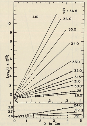
- Townsend studied the relationship between E/p as a function of x, where x is the separation distance between the plates. His study was based on the photoelectron emission from the cathode by ultraviolet light at high uniform electric field up to 30kV/cm and 1 atm pressure.
- He plotted different values for E/p, he found that the slope of the line is which is "the number of the new electrons created by single electron in 1 cm path in the filed direction in a gas at appropriately high E/p" <ref name="loeb"/> . Townsend plotted against the distance of separation x, he concluded the following equation
to calculate (the slope) for different values of E/p as shown in the figure:
- Townsend studied as a function of E/p for a given gas, he founded ,for different values of p,
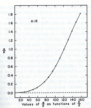
experimentally is different from expected value calculated, but the plots met in values when it represented the relationship between /p as a function of E/p as shwon in the figure below.
- The relationship between /p and E/p is shown below. However, the equation can not predict all the values of /p accurately for different values of E/p, i.e having a single analytical function to fit the experimental results for a gas does not exist, because /p is dependent on the number of electrons produced which changes as the average energy distribution of the ionizing electrons changes <ref name="loeb"/>.
- Theoretical evaluation of as a function of E/p
- The first attempt was done by Townsend when the experimental data were limited by the to the high E/p.
Townsend's Second Coefficient
Boundary Element Method (BEM)
Boundary Element Method is used to solve Laplace or Poisson Equation, a function u(x,y,z) is solved on the domain boundary and the function partial derivatives are evaluated by integrating on the number of elements on the boundary.<ref name="Kuffel"> Kuffel, W. S. Zaengl, J. Kuffel, High voltage engineering: fundamentals, Biddle Ltd, 2nd edition, 2000 </ref>.
References
<references/>

