Difference between revisions of "Mlr Summ TF"
Jump to navigation
Jump to search
| Line 19: | Line 19: | ||
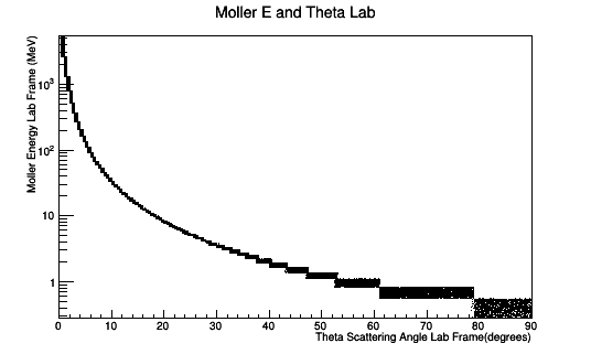
| − | [[File:MolEThetaLabFullStudy.png|frame|center|alt=Moller Electron Energy vs Angle Theta in Lab Frame|'''Figure 2:''' Using the theoretical differential cross section, the distribution of Moller electrons for a CM energy of approximately 53Mev can be distributed through the CM scattering angle Theta. Using Lorentz transformations, these distributions can be transformed to the lab frame. At around 60 degrees in the lab the Moller electron has an energy of close to 1 | + | [[File:MolEThetaLabFullStudy.png|frame|center|alt=Moller Electron Energy vs Angle Theta in Lab Frame|'''Figure 2:''' Using the theoretical differential cross section, the distribution of Moller electrons for a CM energy of approximately 53Mev can be distributed through the CM scattering angle Theta. Using Lorentz transformations, these distributions can be transformed to the lab frame. At around 60 degrees in the lab the Moller electron has an energy of close to 1 MeV. Such a low energy does not allow the Moller electron to leave the constrains of the target where they are created.]] |
Revision as of 05:36, 28 August 2018
VanWasshenova_Thesis#Mlr_Summ_TF
Moller Summary
Scattering Xsect

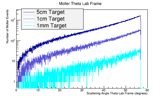
Figure 1: GEANT4 Simulation for the Moller electron scattering angle theta distribution for 6E6 incident 11 GeV electrons in the Lab frame of reference. The LH2 target reduces the mean free path of the Moller electron to around 60 degrees in the lab frame. This property of limiting the Moller angle is independent of the target length.
https://wiki.iac.isu.edu/index.php/Converting_to_barns

Figure 2: Using the theoretical differential cross section, the distribution of Moller electrons for a CM energy of approximately 53Mev can be distributed through the CM scattering angle Theta. Using Lorentz transformations, these distributions can be transformed to the lab frame. At around 60 degrees in the lab the Moller electron has an energy of close to 1 MeV. Such a low energy does not allow the Moller electron to leave the constrains of the target where they are created.

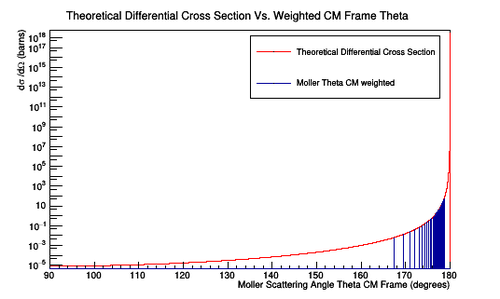
Figure 3a: A plot of the number of Moller scattering angle theta in the center of mass frame versus the theoretical differential cross section. The width of the bins is 0.001 degrees for the angles in the center of mass frame corresponding to angles of 5 to 40 degrees in the lab frame. A weight has been assigned for each value in theta which will give the theoretical differential cross section when applied.

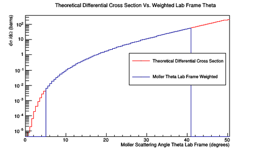
Figure 3b: A plot of the number of Moller scattering angle theta in the lab frame versus the theoretical differential cross section. The width of the bins is 0.5 degrees for the angles in the lab frame. A weight has been assigned for each value in theta which will give the theoretical differential cross section when applied.
Baseline
Moller events using an lH2 target geometry No Raster
DC
Beamline
Magnet Components
FTOn
FTOff
clas12
DC hits -vs- Solenoid
With the Torus at zero Magnetic field the solenoid is changes to show how moller electrons move off the faces of R1 DC.
With Magnet Components


Without Magnet Components


With Only S1R1 DC
What happens when Endplate material is vacuum?

Moller Electron Events(1st hits)

Photons Hits in R1

Tomography


Moller events using an dual polarized target geometry with Raster
Photon Hits in R1 when Raster size has radius of 0.2 cm
Moller rate -vs- length of a single taerget
0.5 cm radius -vs- Z
Target is a one 0.5 cm radius cylinder of length Z.
By how much does the moller rate change at full field ?