Difference between revisions of "Mlr Summ TF"
Jump to navigation
Jump to search
| Line 26: | Line 26: | ||
FTOff | FTOff | ||
| + | |||
| + | clas12 | ||
Revision as of 21:29, 27 August 2018
VanWasshenova_Thesis#Mlr_Summ_TF
Moller Summary
Scattering Xsect
https://wiki.iac.isu.edu/index.php/Converting_to_barns
Moller E -vs- Theta in lab

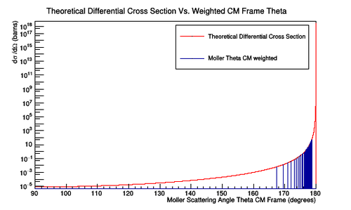
Figure 4a: A plot of the number of Moller scattering angle theta in the center of mass frame versus the theoretical differential cross section. The width of the bins is 0.001 degrees for the angles in the center of mass frame corresponding to angles of 5 to 40 degrees in the lab frame. A weight has been assigned for each value in theta which will give the theoretical differential cross section when applied.

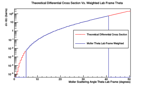
Figure 4b: A plot of the number of Moller scattering angle theta in the lab frame versus the theoretical differential cross section. The width of the bins is 0.5 degrees for the angles in the lab frame. A weight has been assigned for each value in theta which will give the theoretical differential cross section when applied.
Baseline
Moller events using an lH2 target geometry No Raster
Beamline
Magnet Components
FTOn
FTOff
clas12
DC hits -vs- Solenoid
With the Torus at zero Magnetic field the solenoid is changes to show how moller electrons move off the faces of R1 DC.
With Magnet Components


Without Magnet Components


With Only S1R1 DC

Moller Electron Events(1st hits)


Photons Hits in R1


Tomography


Moller events using an dual polarized target geometry with Raster
Photon Hits in R1 when Raster size has radius of 0.2 cm
Moller rate -vs- length of a single taerget
0.5 cm radius -vs- Z
Target is a one 0.5 cm radius cylinder of length Z.
By how much does the moller rate change at full field ?